HP Pavilion TouchSmart 14-f040ca HP Pavillion Sleekbook 14 Maintenance and Ser - Page 59
System board, the defective system board and installed on the replacement system board
 |
View all HP Pavilion TouchSmart 14-f040ca manuals
Add to My Manuals
Save this manual to your list of manuals |
Page 59 highlights
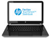
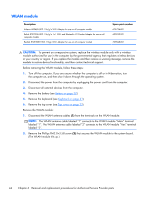
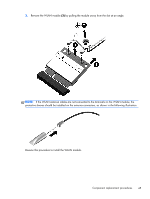
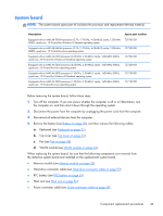
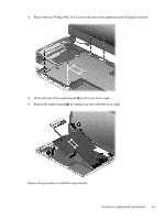
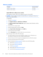
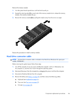
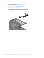
System board NOTE: The system board spare part kit includes the processor and replacement thermal material. Description Equipped with an AMD A8-5545M processor (2.70-/1.70-GHz, 4.00-MB L2 cache, 1333-MHz DDR3L, quad core, 19 W) and the Windows 8 Standard operating system Equipped with an AMD A8-5545M processor (2.70-/1.70-GHz, 4.00-MB L2 cache, 1333-MHz DDR3L, quad core, 19 W) and the Linux operating system Equipped with an AMD A6-5200 processor (2.00-GHz, 2.00-MB L2 cache, 1600-MHz DDR3L, quad core, 25 W) and the Windows 8 Standard operating system Equipped with an AMD A6-5200 processor (2.00-GHz, 2.00-MB L2 cache, 1600-MHz DDR3L, quad core, 25 W) and the Linux operating system Equipped with an AMD A4-5000 processor (1.50-GHz, 2.00-MB L2 cache, 1600-MHz DDR3L, quad core, 15 W) and the Windows 8 Standard operating system Equipped with an AMD A4-5000 processor (1.50-GHz, 2.00-MB L2 cache, 1600-MHz DDR3L, quad core, 15 W) and the Linux operating system Spare part number 727202-501 727202-001 727200-501 727200-001 727199-501 727199-001 Before removing the system board, follow these steps: 1. Turn off the computer. If you are unsure whether the computer is off or in Hibernation, turn the computer on, and then shut it down through the operating system. 2. Disconnect the power from the computer by unplugging the power cord from the computer. 3. Disconnect all external devices from the computer. 4. Remove the battery (see Battery on page 30), and then remove the following cables: a. Keyboard (see Keyboard on page 31). b. Top cover (see Top cover on page 33). c. Fan (see Fan on page 42). d. WLAN module (see WLAN module on page 44). When replacing the system board, be sure that the following components are removed from the defective system board and installed on the replacement system board: ● Memory module (see Memory module on page 52) ● Hard drive connector cable (see Hard drive connector cable on page 53) ● RTC battery (see RTC battery on page 55) ● Heat sink (see Heat sink on page 56) ● Power connector cable (see Power connector cable on page 58) Component replacement procedures 49
-
 1
1 -
2
-
3
-
4
-
5
-
6
-
7
-
8
-
9
-
10
-
11
-
12
-
13
-
14
-
15
-
16
-
17
-
18
-
19
-
20
-
21
-
22
-
23
-
24
-
25
-
26
-
27
-
28
-
29
-
30
-
31
-
32
-
33
-
34
-
35
-
36
-
37
-
38
-
39
-
40
-
41
-
42
-
43
-
44
-
45
-
46
-
47
-
48
-
49
-
50
-
51
-
52
-
53
-
 54
54 -
 55
55 -
 56
56 -
 57
57 -
 58
58 -
 59
59 -
 60
60 -
 61
61 -
 62
62 -
 63
63 -
 64
64 -
65
-
66
-
67
-
68
-
69
-
70
-
71
-
72
-
73
-
74
-
75
-
76
-
77
-
78
-
79
-
80
-
81
-
82
-
83
-
84
-
85
-
86
-
87
-
88
-
89
-
90
-
91
 |
 |