HP Pavilion dv3-1100 HP Pavilion dv3 Entertainment PC - Maintenance and Servic - Page 66
Fan/heat sink assembly, Disconnect the fan cable
 |
View all HP Pavilion dv3-1100 manuals
Add to My Manuals
Save this manual to your list of manuals |
Page 66 highlights
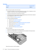
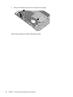
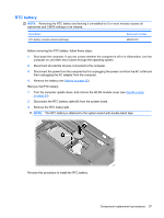
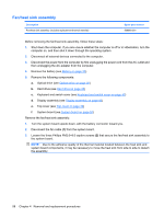
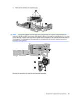
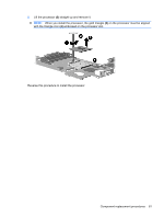
Fan/heat sink assembly Description Fan/heat sink assembly (includes replacement thermal material) Spare part number 506960-001 Before removing the fan/heat sink assembly, follow these steps: 1. Shut down the computer. If you are unsure whether the computer is off or in Hibernation, turn the computer on, and then shut it down through the operating system. 2. Disconnect all external devices connected to the computer. 3. Disconnect the power from the computer by first unplugging the power cord from the AC outlet and then unplugging the AC adapter from the computer. 4. Remove the battery (see Battery on page 32). 5. Remove the following components: a. Optical drive (see Optical drive on page 35) b. Hard drive (see Hard drive on page 38) c. Keyboard and switch cover (see Keyboard and switch cover on page 40) d. Display assembly (see Display assembly on page 43) e. Top cover (see Top cover on page 49) f. System board (see System board on page 52) Remove the fan/heat sink assembly: 1. Turn the system board upside down, with the battery connector toward you. 2. Disconnect the fan cable (1) from the system board. 3. Loosen the three Phillips PM2.0×8.0 captive screws (2) that secure the fan/heat sink assembly to the system board. NOTE: Due to the adhesive quality of the thermal material located between the heat sink and system board components, it may be necessary to move the heat sink from side to side to detach the assembly. 58 Chapter 4 Removal and replacement procedures
-
 1
1 -
2
-
3
-
4
-
5
-
6
-
7
-
8
-
9
-
10
-
11
-
12
-
13
-
14
-
15
-
16
-
17
-
18
-
19
-
20
-
21
-
22
-
23
-
24
-
25
-
26
-
27
-
28
-
29
-
30
-
31
-
32
-
33
-
34
-
35
-
36
-
37
-
38
-
39
-
40
-
41
-
42
-
43
-
44
-
45
-
46
-
47
-
48
-
49
-
50
-
51
-
52
-
53
-
54
-
55
-
56
-
57
-
58
-
59
-
60
-
 61
61 -
 62
62 -
 63
63 -
 64
64 -
 65
65 -
 66
66 -
 67
67 -
 68
68 -
 69
69 -
 70
70 -
 71
71 -
72
-
73
-
74
-
75
-
76
-
77
-
78
-
79
-
80
-
81
-
82
-
83
-
84
-
85
-
86
-
87
-
88
-
89
-
90
-
91
-
92
-
93
-
94
-
95
-
96
-
97
-
98
-
99
-
100
-
101
-
102
-
103
-
104
-
105
-
106
-
107
-
108
-
109
-
110
-
111
-
112
-
113
-
114
 |
 |
