HP Pavilion dv4-1300 HP Pavilion dv4 Entertainment PC - Maintenance and Servic - Page 123
Heat sink assembly for discrete graphics system
 |
View all HP Pavilion dv4-1300 manuals
Add to My Manuals
Save this manual to your list of manuals |
Page 123 highlights
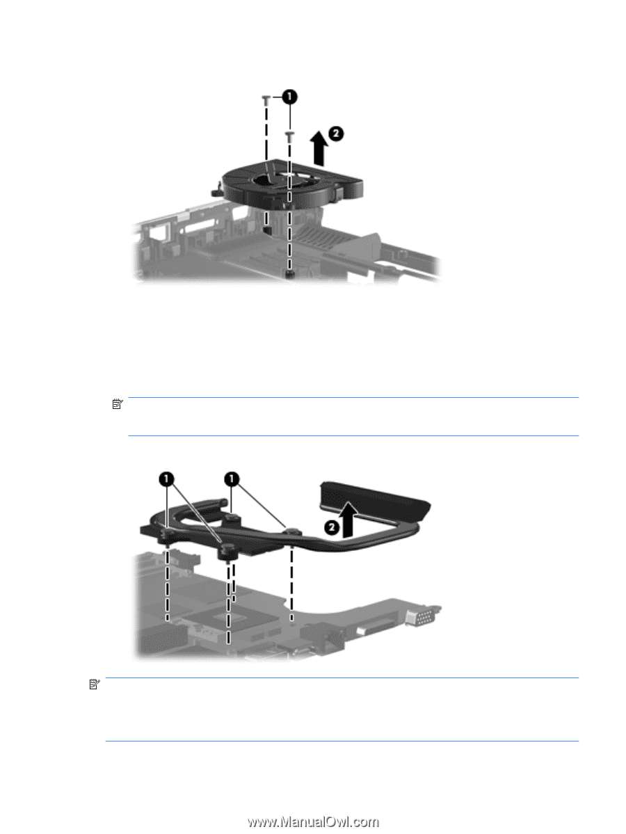
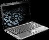
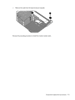
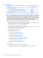
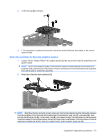
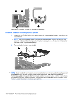
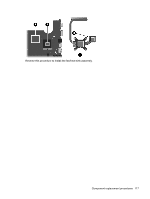
3. Lift the fan up (2) to remove. 4. If it is necessary to replace the heat sink, select the section following that relates to the correct system board. Heat sink assembly for discrete graphics system 1. Loosen the four Phillips PM2.0×10.0 captive screws (1) that secure the heat sink assembly to the system board. NOTE: Due to the adhesive quality of the thermal material located between the fan/heat sink assembly and system board components, it may be necessary to move the fan/heat sink assembly from side to side to detach the assembly. 2. Remove the fan/heat sink assembly (2). NOTE: Each time the fan and heat sink are removed, the thermal material must be thoroughly cleaned from the surfaces of the heat sink and system board components: heat sink (1), processor (2), heat sink (3), Northbridge clip (4), nVidia video chip (5), and capacitors (6). Thermal pads and thermal paste must be installed on all surfaces before the fan and heat sink are reinstalled. Thermal pads and thermal paste are included with all fan, heat sink, system board, and processor spare part kits. Component replacement procedures 115
-
 1
1 -
2
-
3
-
4
-
5
-
6
-
7
-
8
-
9
-
10
-
11
-
12
-
13
-
14
-
15
-
16
-
17
-
18
-
19
-
20
-
21
-
22
-
23
-
24
-
25
-
26
-
27
-
28
-
29
-
30
-
31
-
32
-
33
-
34
-
35
-
36
-
37
-
38
-
39
-
40
-
41
-
42
-
43
-
44
-
45
-
46
-
47
-
48
-
49
-
50
-
51
-
52
-
53
-
54
-
55
-
56
-
57
-
58
-
59
-
60
-
61
-
62
-
63
-
64
-
65
-
66
-
67
-
68
-
69
-
70
-
71
-
72
-
73
-
74
-
75
-
76
-
77
-
78
-
79
-
80
-
81
-
82
-
83
-
84
-
85
-
86
-
87
-
88
-
89
-
90
-
91
-
92
-
93
-
94
-
95
-
96
-
97
-
98
-
99
-
100
-
101
-
102
-
103
-
104
-
105
-
106
-
107
-
108
-
109
-
110
-
111
-
112
-
113
-
114
-
115
-
116
-
117
-
 118
118 -
 119
119 -
 120
120 -
 121
121 -
 122
122 -
 123
123 -
 124
124 -
 125
125 -
 126
126 -
 127
127 -
 128
128 -
129
-
130
-
131
-
132
-
133
-
134
-
135
-
136
-
137
-
138
-
139
-
140
-
141
-
142
-
143
-
144
-
145
-
146
-
147
-
148
-
149
-
150
-
151
-
152
-
153
-
154
-
155
-
156
-
157
-
158
-
159
-
160
-
161
-
162
-
163
-
164
-
165
-
166
-
167
-
168
-
169
-
170
-
171
-
172
-
173
-
174
-
175
-
176
-
177
-
178
-
179
-
180
-
181
-
182
-
183
-
184
-
185
-
186
-
187
-
188
-
189
-
190
-
191
-
192
-
193
-
194
-
195
-
196
 |
 |