HP Pavilion dv6-2100 HP Pavilion dv6 Entertainment PC - Maintenance and Servic - Page 125
Index, Digital Media Slot
 |
View all HP Pavilion dv6-2100 manuals
Add to My Manuals
Save this manual to your list of manuals |
Page 125 highlights
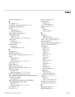
Index 1394 pin assignments 9-1 A AC adapter 2-11 AC adapter, spare part number 3-11, 3-12 administrator password 5-3 antenna components 1-3 spare part number 3-3 audio, product description 1-2 audio/infrared board removal 4-34 spare part number 3-6, 3-14, 4-34 audio-in jack location 2-5 pin assignments 9-2 audio-out jack location 2-5 pin assignments 9-1, 9-2 B backing up 8-2 backup, hard drive 8-3 base enclosure, spare part number 3-6, 3-17 battery illustrated 2-11 removal 4-7 spare part number 3-7, 3-12, 4-7 battery bay 2-8 battery light 2-2 battery release latch 2-8 Bluetooth cable, spare part number 3-19 Bluetooth module removal 4-24 spare part number 3-3, 3-17, 4-24 Bluetooth module cable, removal 4-24 Blu-ray ROM with LightScribe DVD±R SuperMulti Double-Layer Drive specifications 6-3 Blu-ray ROM with LightScribe DVD±R/RW SuperMulti Double-Layer Drive removal 4-9 spare part number 3-7, 3-13, 4-9 boot options 5-4 boot order 5-4 bottom components 2-8 built-in device modem 4-33 wireless button 2-3 button components 2-3 buttons power 2-3 volume mute 2-3 C Cable Kit illustrated 3-10 spare part number 3-10, 3-17 cables, service considerations 4-1 caps lock light 2-2 carrying case, spare part number 3-12 chipset, product description 1-1 components bottom 2-8 buttons 2-3 display 2-9 front 2-5 hardware 2-11 keys 2-4 left-side 2-7 lights 2-2 power cord 2-11 rear 2-6 right-side 2-6 top 2-1 TouchPad 2-1 wireless antenna 2-9 computer feet locations 4-6 spare part number 4-6 computer specifications 6-1 connectors power 2-6 service considerations 4-1 creating recovery discs 8-1 creating recovery points 8-3 D Diagnostics menu 5-4 Digital Media Slot 2-7 Maintenance and Service Guide Index-1
-
 1
1 -
2
-
3
-
4
-
5
-
6
-
7
-
8
-
9
-
10
-
11
-
12
-
13
-
14
-
15
-
16
-
17
-
18
-
19
-
20
-
21
-
22
-
23
-
24
-
25
-
26
-
27
-
28
-
29
-
30
-
31
-
32
-
33
-
34
-
35
-
36
-
37
-
38
-
39
-
40
-
41
-
42
-
43
-
44
-
45
-
46
-
47
-
48
-
49
-
50
-
51
-
52
-
53
-
54
-
55
-
56
-
57
-
58
-
59
-
60
-
61
-
62
-
63
-
64
-
65
-
66
-
67
-
68
-
69
-
70
-
71
-
72
-
73
-
74
-
75
-
76
-
77
-
78
-
79
-
80
-
81
-
82
-
83
-
84
-
85
-
86
-
87
-
88
-
89
-
90
-
91
-
92
-
93
-
94
-
95
-
96
-
97
-
98
-
99
-
100
-
101
-
102
-
103
-
104
-
105
-
106
-
107
-
108
-
109
-
110
-
111
-
112
-
113
-
114
-
115
-
116
-
117
-
118
-
119
-
 120
120 -
 121
121 -
 122
122 -
 123
123 -
 124
124 -
 125
125 -
 126
126 -
 127
127 -
 128
128 -
 129
129
 |
 |