HP Pavilion dv7-3100 HP Pavilion dv7 Entertainment PC - Maintenance and Servic - Page 80
Modem module cable
 |
View all HP Pavilion dv7-3100 manuals
Add to My Manuals
Save this manual to your list of manuals |
Page 80 highlights
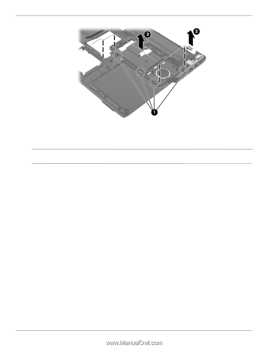
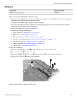
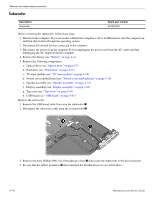
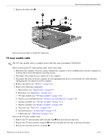
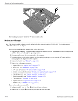
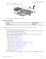
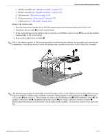
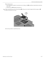
Removal and replacement procedures Reverse this procedure to install the TV tuner module cable. Modem module cable ✎ The modem module cable is available in the Cable Kit, spare part number 516328-001. The modem module cable includes the RJ-11 jack. Before removing the modem module cable, follow these steps: 1. Shut down the computer. If you are unsure whether the computer is off or in Hibernation, turn the computer on, and then shut it down through the operating system. 2. Disconnect all external devices connected to the computer. 3. Disconnect the power from the computer by first unplugging the power cord from the AC outlet and then unplugging the AC adapter from the computer. 4. Remove the battery (see "Battery" on page 4-6). 5. Remove the following components: a. Optical drive (see "Optical drive" on page 4-7) b. Hard drive (see "Hard drive" on page 4-11) c. TV tuner module (see "TV tuner module" on page 4-18) d. Switch cover and keyboard (see "Switch cover and keyboard" on page 4-19) e. Speaker assembly (see "Speaker assembly" on page 4-23) f. Display assembly (see "Display assembly" on page 4-25) g. Top cover (see "Top cover" on page 4-34) h. System board (see "System board" on page 4-37) i. USB board (see "USB board" on page 4-41) Remove the modem module cable: 1. Release the cable from the clips 1 built into the base enclosure. 2. Remove the RJ-11 jack 2 from the clip built into the base enclosure. 4-44 Maintenance and Service Guide
-
 1
1 -
2
-
3
-
4
-
5
-
6
-
7
-
8
-
9
-
10
-
11
-
12
-
13
-
14
-
15
-
16
-
17
-
18
-
19
-
20
-
21
-
22
-
23
-
24
-
25
-
26
-
27
-
28
-
29
-
30
-
31
-
32
-
33
-
34
-
35
-
36
-
37
-
38
-
39
-
40
-
41
-
42
-
43
-
44
-
45
-
46
-
47
-
48
-
49
-
50
-
51
-
52
-
53
-
54
-
55
-
56
-
57
-
58
-
59
-
60
-
61
-
62
-
63
-
64
-
65
-
66
-
67
-
68
-
69
-
70
-
71
-
72
-
73
-
74
-
 75
75 -
 76
76 -
 77
77 -
 78
78 -
 79
79 -
 80
80 -
 81
81 -
 82
82 -
 83
83 -
 84
84 -
 85
85 -
86
-
87
-
88
-
89
-
90
-
91
-
92
-
93
-
94
-
95
-
96
-
97
-
98
-
99
-
100
-
101
-
102
-
103
-
104
-
105
-
106
-
107
-
108
-
109
-
110
-
111
-
112
-
113
-
114
-
115
-
116
-
117
-
118
-
119
-
120
-
121
-
122
-
123
-
124
-
125
-
126
-
127
-
128
-
129
-
130
-
131
-
132
-
133
-
134
-
135
-
136
-
137
-
138
-
139
-
140
 |
 |