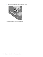
HP ProBook 4326s HP ProBook 4325s, 4326s and 4425s Notebook PCs - Maintenance - Page 75
The black WLAN antenna cable is connected to the WLAN module Main terminal.
 |
View all HP ProBook 4326s manuals
Add to My Manuals
Save this manual to your list of manuals |
Page 75 highlights
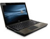
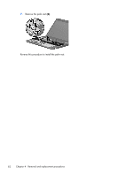
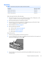
4. Remove the battery (see Battery on page 44). 5. Remove the following components: a. Switch cover (see Switch cover on page 46) b. Keyboard (see Keyboard on page 48) c. Palm rest (see Palm rest on page 60) Remove the WLAN module: 1. Position the computer right-side up with the front toward you. 2. Disconnect the WLAN antenna cables from the terminals on the WLAN module. NOTE: The black WLAN antenna cable is connected to the WLAN module "Main" terminal. The white WLAN antenna cable is connected to the WLAN module "Aux" terminal. 3. Remove the two Phillips PM2.5×3.0 screws that secure the WLAN module to the computer. (The edge of the module opposite the slot rises away from the computer.) Component replacement procedures 67
-
 1
1 -
2
-
3
-
4
-
5
-
6
-
7
-
8
-
9
-
10
-
11
-
12
-
13
-
14
-
15
-
16
-
17
-
18
-
19
-
20
-
21
-
22
-
23
-
24
-
25
-
26
-
27
-
28
-
29
-
30
-
31
-
32
-
33
-
34
-
35
-
36
-
37
-
38
-
39
-
40
-
41
-
42
-
43
-
44
-
45
-
46
-
47
-
48
-
49
-
50
-
51
-
52
-
53
-
54
-
55
-
56
-
57
-
58
-
59
-
60
-
61
-
62
-
63
-
64
-
65
-
66
-
67
-
68
-
69
-
 70
70 -
 71
71 -
 72
72 -
 73
73 -
 74
74 -
 75
75 -
 76
76 -
 77
77 -
 78
78 -
 79
79 -
 80
80 -
81
-
82
-
83
-
84
-
85
-
86
-
87
-
88
-
89
-
90
-
91
-
92
-
93
-
94
-
95
-
96
-
97
-
98
-
99
-
100
-
101
-
102
-
103
-
104
-
105
-
106
-
107
-
108
-
109
-
110
-
111
-
112
-
113
-
114
-
115
-
116
-
117
-
118
-
119
-
120
-
121
-
122
-
123
-
124
-
125
-
126
-
127
-
128
-
129
-
130
-
131
-
132
-
133
-
134
-
135
-
136
-
137
-
138
-
139
-
140
-
141
-
142
-
143
-
144
-
145
-
146
-
147
-
148
-
149
-
150
-
151
-
152
-
153
-
154
-
155
-
156
-
157
-
158
-
159
-
160
-
161
-
162
 |
 |
4.
Remove the battery (see
Battery
on page
44
).
5.
Remove the following components:
a.
Switch cover (see
Switch cover
on page
46
)
b.
Keyboard (see
Keyboard
on page
48
)
c.
Palm rest (see
Palm rest
on page
60
)
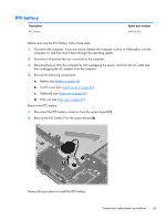
Remove the WLAN module:
1.
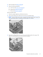
Position the computer right-side up with the front toward you.
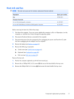
2.
Disconnect the WLAN antenna cables from the terminals on the WLAN module.
NOTE:
The black WLAN antenna cable is connected to the WLAN module “Main” terminal. The
white WLAN antenna cable is connected to the WLAN module “Aux” terminal.
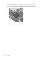
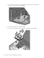
3.
Remove the two Phillips PM2.5×3.0 screws that secure the WLAN module to the computer. (The
edge of the module opposite the slot rises away from the computer.)
Component replacement procedures
67