HP ProBook 5320m HP ProBook 5320m Notebook PC Maintenance and Service Guide - Page 130
Display Cable Kit, HP SpareKey Enrollment
 |
View all HP ProBook 5320m manuals
Add to My Manuals
Save this manual to your list of manuals |
Page 130 highlights
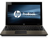
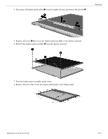
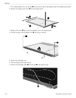
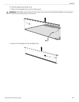
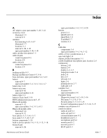
Index USB port 8-4 connectors, service considerations 4-1 creating a backup 8-5 D device configurations 5-5, 5-6, 5-10, 5-11, 5-17, 5-18 Diagnostics menu 5-4, 5-10, 5-16 Disk Sanitizer 5-15 display assembly removal 4-43 spare part numbers 3-3, 3-13, 4-43 display bezel illustrated 3-7, 3-13 removal 4-44 spare part number 3-7, 3-13, 4-45 Display Cable Kit illustrated 3-7 spare part number 3-7, 3-13 display components illustrated 2-2, 2-3 recycling 10-1 spare part numbers 3-7 display enclosure illustrated 3-7, 3-13 spare part number 3-7, 3-13 display hinge illustrated 3-7, 3-11 removal 4-46 spare part number 3-7, 3-11, 4-46 display inverter, removal 10-3 display panel cable illustrated 3-7 removal 4-47 spare part numbers 4-47 display panel, product description 1-1 display switch, location 2-2 DisplayPort, location 2-9 drive light 2-8 DriveLock password 5-15 DriveLock, automatic 5-15 drives, boot order 5-5, 5-10, 5-17 E electrostatic discharge 4-2 equipment guidelines 4-4 esc key 2-5 Ethernet, product description 1-2 external media card, product description 1-2 external monitor port connector pinout 8-2 location 2-9 Index-2 F f11 recovery 8-7 fan removal 4-36 spare part number 3-4, 3-13, 4-36 feet locations 4-6 spare part number 4-6 File menu 5-3, 5-8, 5-14 fn key 2-5 front components 2-8 function keys 2-5 G graphics, product description 1-1 grounding equipment and methods 4-2 H hard drive precautions 4-2 product description 1-1 removal 4-9 spare part numbers 3-5, 3-8, 3-11, 4-9 specifications 6-3 hard drive bay 2-10 hard drive recovery 8-7 headphone jack connector pinout 8-1 location 2-8 heat sink removal 4-36 spare part number 4-36 hinge illustrated 3-7, 3-11 removal 4-46 spare part number 3-7, 3-11, 4-46 HP SpareKey Enrollment 5-15 J jacks audio-in 2-8 audio-out 2-8 combo headphone microphone 2-8 headphone 2-8 microphone 2-8 network 2-9 RJ-45 2-9 K key components 2-5 keyboard product description 1-2 removal 4-23 spare part numbers 3-3, 3-13, 3-14, 4-23 Maintenance and Service Guide
-
 1
1 -
2
-
3
-
4
-
5
-
6
-
7
-
8
-
9
-
10
-
11
-
12
-
13
-
14
-
15
-
16
-
17
-
18
-
19
-
20
-
21
-
22
-
23
-
24
-
25
-
26
-
27
-
28
-
29
-
30
-
31
-
32
-
33
-
34
-
35
-
36
-
37
-
38
-
39
-
40
-
41
-
42
-
43
-
44
-
45
-
46
-
47
-
48
-
49
-
50
-
51
-
52
-
53
-
54
-
55
-
56
-
57
-
58
-
59
-
60
-
61
-
62
-
63
-
64
-
65
-
66
-
67
-
68
-
69
-
70
-
71
-
72
-
73
-
74
-
75
-
76
-
77
-
78
-
79
-
80
-
81
-
82
-
83
-
84
-
85
-
86
-
87
-
88
-
89
-
90
-
91
-
92
-
93
-
94
-
95
-
96
-
97
-
98
-
99
-
100
-
101
-
102
-
103
-
104
-
105
-
106
-
107
-
108
-
109
-
110
-
111
-
112
-
113
-
114
-
115
-
116
-
117
-
118
-
119
-
120
-
121
-
122
-
123
-
124
-
 125
125 -
 126
126 -
 127
127 -
 128
128 -
 129
129 -
 130
130 -
 131
131 -
 132
132 -
 133
133
 |
 |