HP ProDesk 600 Maintenance and Service Guide - HP ProDesk 600 G1 Tower, HP Pro
HP ProDesk 600 Manual
 |
View all HP ProDesk 600 manuals
Add to My Manuals
Save this manual to your list of manuals |
HP ProDesk 600 manual content summary:
- HP ProDesk 600 | Maintenance and Service Guide - HP ProDesk 600 G1 Tower, HP Pro - Page 1
Maintenance and Service Guide HP ProDesk 600 G1 Tower HP ProDesk 600 G1 Small Form Factor - HP ProDesk 600 | Maintenance and Service Guide - HP ProDesk 600 G1 Tower, HP Pro - Page 2
HP products and services are set forth in the express warranty statements accompanying such products and services. Nothing herein should be construed as constituting an additional warranty. HP Number: 723281-001 Product notice This guide describes features that are common to most models. Some - HP ProDesk 600 | Maintenance and Service Guide - HP ProDesk 600 G1 Tower, HP Pro - Page 3
About This Book WARNING! Text set off in this manner indicates that failure to follow directions could result in bodily harm or loss of life. CAUTION: Text set off in this manner indicates that failure to follow directions could result in damage to equipment or loss of information. NOTE: Text set - HP ProDesk 600 | Maintenance and Service Guide - HP ProDesk 600 G1 Tower, HP Pro - Page 4
iv About This Book - HP ProDesk 600 | Maintenance and Service Guide - HP ProDesk 600 G1 Tower, HP Pro - Page 5
number location ...7 Tower (TWR) ...7 Small Form Factor (SFF 7 2 Activating and Customizing the Software 8 Activating and customizing the software in Windows 7 8 Activating the Windows operating system 8 Downloading Windows 7 updates 9 Installing or upgrading device drivers 9 Customizing the - HP ProDesk 600 | Maintenance and Service Guide - HP ProDesk 600 G1 Tower, HP Pro - Page 6
Small Form Factor (SFF) chassis spare parts 20 Computer major components 20 Cables ...21 data cable ...36 SMART ATA drives ...36 Cable management ...36 5 Removal and replacement procedures: Tower (TWR 37 Preparation for disassembly ...37 Access panel ...38 Front bezel security ...39 Front bezel - HP ProDesk 600 | Maintenance and Service Guide - HP ProDesk 600 G1 Tower, HP Pro - Page 7
Cover Lock (solenoid lock 74 Hood sensor ...77 Fan ...78 Power supply ...80 System board ...83 6 Removal and replacement procedures: Small Form Factor (SFF 85 Preparation for disassembly ...85 Access panel ...86 Front bezel ...87 Front bezel security ...88 Bezel blanks ...90 Memory ...91 DIMMs - HP ProDesk 600 | Maintenance and Service Guide - HP ProDesk 600 G1 Tower, HP Pro - Page 8
board ...129 Changing from desktop to tower configuration 130 7 Computer Setup Troubleshooting without diagnostics 148 Safety and comfort ...148 Before you call for technical support 148 Helpful hints ...149 Solving general problems ...151 Solving power problems ...155 Solving hard drive problems - HP ProDesk 600 | Maintenance and Service Guide - HP ProDesk 600 G1 Tower, HP Pro - Page 9
jumper 201 Clearing and resetting the CMOS 202 11 HP PC Hardware Diagnostics 204 Why run HP PC Hardware Diagnostics - UEFI 204 How to access and run HP PC Hardware Diagnostics - UEFI 204 Downloading HP PC Hardware Diagnostics to a USB device 205 12 System backup and recovery 206 Backing - HP ProDesk 600 | Maintenance and Service Guide - HP ProDesk 600 G1 Tower, HP Pro - Page 10
217 System Recovery using recovery media (select models only 217 Using HP Recovery Disc operating system discs (select models only 218 Appendix cord requirements 226 Country-specific requirements 227 Appendix D Specifications 228 TWR specifications ...228 SFF specifications ...229 Index ...231 - HP ProDesk 600 | Maintenance and Service Guide - HP ProDesk 600 G1 Tower, HP Pro - Page 11
hardware and software installed in the computer, run the diagnostic utility (included on some computer models only). NOTE: Both computer models can be used in a tower orientation or a desktop orientation. Tower (TWR) Standard configuration features 1 - HP ProDesk 600 | Maintenance and Service Guide - HP ProDesk 600 G1 Tower, HP Pro - Page 12
Small Form Factor (SFF) 2 Chapter 1 Product features - HP ProDesk 600 | Maintenance and Service Guide - HP ProDesk 600 G1 Tower, HP Pro - Page 13
icon in the Windows taskbar. NOTE: The Power On Light is normally white when the power is on. If it is flashing red, there is a problem with the computer and it is displaying a diagnostic code. Refer to the Maintenance and Service Guide to interpret the code. Tower (TWR) front panel components 3 - HP ProDesk 600 | Maintenance and Service Guide - HP ProDesk 600 G1 Tower, HP Pro - Page 14
Small Form Factor (SFF) front panel components Drive configuration may vary by model. Some models have a bezel blank covering one or more drive bays. 1 Slim Optical Drive (optional) 5 Headphone Connector 2 USB 2.0 Ports (black) 6 Dual-State Power Button 3 USB 3.0 Ports (blue) 7 Hard Drive - HP ProDesk 600 | Maintenance and Service Guide - HP ProDesk 600 G1 Tower, HP Pro - Page 15
Connector 11 Line-In Audio Connector (blue) 6 USB 3.0 Ports (blue) NOTE: An optional second serial port and an optional parallel port are available from HP. When a device is plugged into the blue can be disabled by changing settings in Computer Setup. Tower (TWR) rear panel components 5 - HP ProDesk 600 | Maintenance and Service Guide - HP ProDesk 600 G1 Tower, HP Pro - Page 16
Small Form Factor (SFF) rear panel components 1 PS/2 Mouse Connector (green) 7 PS/2 Keyboard Connector (purple) 2 RJ-45 Network Connector 8 DisplayPort Monitor Connectors 3 Serial Connector 4 USB 2.0 Ports (black) 9 VGA Monitor Connector 10 USB 3.0 Ports (blue) 5 Line-In Audio - HP ProDesk 600 | Maintenance and Service Guide - HP ProDesk 600 G1 Tower, HP Pro - Page 17
Serial number location Each computer has a unique serial number and a product ID number that are located on the exterior of the computer. Keep these numbers available for use when contacting customer service for assistance. Tower (TWR) Small Form Factor (SFF) Serial number location 7 - HP ProDesk 600 | Maintenance and Service Guide - HP ProDesk 600 G1 Tower, HP Pro - Page 18
to 10 minutes. Carefully read and follow the instructions on the screen to complete the activation. We recommend that you register your computer with HP during operating system setup so you can receive important software updates, facilitate support questions, and sign up for special offers. CAUTION - HP ProDesk 600 | Maintenance and Service Guide - HP ProDesk 600 G1 Tower, HP Pro - Page 19
drivers. Obtain the latest support software, including support software for the operating system, from http://www.hp.com/support. Select your country and language, select Download drivers -click on the Windows desktop, then click Personalize to follow the instructions on the screen to complete the activation. - HP ProDesk 600 | Maintenance and Service Guide - HP ProDesk 600 G1 Tower, HP Pro - Page 20
support questions, and sign up for special offers. You can also register your computer with HP using the Register with HP app PC Settings. 3. Click Personalize to change the display settings. To customize the Desktop: 1. Click the Desktop app on the Start screen. 2. Right-click on the desktop - HP ProDesk 600 | Maintenance and Service Guide - HP ProDesk 600 G1 Tower, HP Pro - Page 21
3 Illustrated parts catalog This chapter provides spare part information for all chassis. Tower (TWR) chassis spare parts Computer major components Tower (TWR) chassis spare parts 11 - HP ProDesk 600 | Maintenance and Service Guide - HP ProDesk 600 G1 Tower, HP Pro - Page 22
with NetClone Memory modules (PC3-12800) 8-GB 4-GB 2-GB Processors (include replacement thermal material) Intel Core i7 4770 (3.4-GHz, 8-MB L3 cache) Intel Core i5 4670 (3.4-GHz, 6-MB L3 cache) Intel Core i5 4570 (3.2-GHz, 6-MB L3 cache) Spare part number 732751-001 732748-001 702452-001 - HP ProDesk 600 | Maintenance and Service Guide - HP ProDesk 600 G1 Tower, HP Pro - Page 23
14 inch, 1 straight end, 1 angled end Hard drive SATA cable, 17.7 inch, 2 straight ends DMS-59 to dual VGA cable Adapter, DisplayPort to VGA Adapter, DisplayPort to DVI Adapter, DisplayPort to HDMI Adapter, -001 657401-001 720216-001 202997-001 487562-001 Tower (TWR) chassis spare parts 13 - HP ProDesk 600 | Maintenance and Service Guide - HP ProDesk 600 G1 Tower, HP Pro - Page 24
sink (includes replacement thermal material) (2) Solenoid lock (3) Speaker (4) Hood sensor (5) Fan Card reader, 14-in-1, USB 3.0, 3.5-inch Optical drive bezel blank Printer port, PCI card HP Ultraslim Keyed Cable Lock Adapter, 2.5-inch hard drive Hard drive grommet for use on 2.5-inch - HP ProDesk 600 | Maintenance and Service Guide - HP ProDesk 600 G1 Tower, HP Pro - Page 25
Item Description USB, HP Elite Washable Wireless, HP Elite USB, optical Foot kit Keyboards PS/2 USB USB, wireless Smart card Smart card, CCID Wireless keyboard, mouse, and dongle Washable Drives Description Hard 646809-001 665961-001 728559-001 661841-001 719157-001 Tower (TWR) chassis spare parts 15 - HP ProDesk 600 | Maintenance and Service Guide - HP ProDesk 600 G1 Tower, HP Pro - Page 26
graphics card, 2 GB Intel PRO/1000 single port GbE NIC, includes bracket HP WLAN 802.11 a/b/g/n 2x2 PCIe module HP WLAN/Bluetooth module Sequential part drive conversion bracket Hard drive grommet for use on 3.5-inch drives DMS-59 to dual VGA cable DisplayPort cable WLAN antennas Adapter, 2.5-inch - HP ProDesk 600 | Maintenance and Service Guide - HP ProDesk 600 G1 Tower, HP Pro - Page 27
to VGA Rear chassis fan Serial port PCI card Hood sensor Printer port, PCI card Hard drive SATA cable, 17.7 inch, , optical Mouse, USB, optical Mouse, wireless Mouse, USB 256 GB Solid-state drive, self-encrypting (SED) Memory module, 8-GB, PC3-12800 HP WLAN 802.11 Tower (TWR) chassis spare parts 17 - HP ProDesk 600 | Maintenance and Service Guide - HP ProDesk 600 G1 Tower, HP Pro - Page 28
efficient 320W, 90% efficient 320W, standard HP Ultraslim Keyed Cable Lock Hard drive carrier Intel Core i7 4770 processor (3.4-GHz, 8-MB L3 cache) Intel Core i5 4570 processor (3.2-GHz, 6-MB L3 cache) Intel Core i5 4670 processor (3.4-GHz, 6-MB L3 cache) 128 GB Solid-state Drive (SSD), TCG Intel PRO - HP ProDesk 600 | Maintenance and Service Guide - HP ProDesk 600 G1 Tower, HP Pro - Page 29
countries and regions except for China Optical drive SATA cable, 14 inch, 1 straight end, 1 angled end Drive power cable Optical drive bezel blank Cable clip HP WLAN/Bluetooth module Tower (TWR) chassis spare parts 19 - HP ProDesk 600 | Maintenance and Service Guide - HP ProDesk 600 G1 Tower, HP Pro - Page 30
Small Form Factor (SFF) chassis spare parts Computer major components Item Description (1) Front bezel (2) Access panel (3) Power supply 240W, 92% efficient 240W, 90% efficient 240W, standard (4) System board (includes - HP ProDesk 600 | Maintenance and Service Guide - HP ProDesk 600 G1 Tower, HP Pro - Page 31
) Intel Core i7 4770 (3.4-GHz, 8-MB L3 cache) Intel Core i5 4670 (3.4-GHz, 6-MB L3 cache) Intel Core i5 4570 angled end Optical drive SATA cable, 19.5 inch, 2 straight ends DMS-59 to dual VGA cable Adapter, DisplayPort to VGA Adapter, DisplayPort Small Form Factor (SFF) chassis spare parts 21 - HP ProDesk 600 | Maintenance and Service Guide - HP ProDesk 600 G1 Tower, HP Pro - Page 32
sink (includes replacement thermal material) (2) Fan duct (3) Speaker (4) Hood sensor Card reader, 14-in-1, USB 3.0, 3.5-inch Optical drive bezel blank Solenoid lock Printer port, PCI card HP Ultraslim Keyed Cable Lock Rubber foot Chassis stand Serial port, PCI card Adapter, 2.5-inch - HP ProDesk 600 | Maintenance and Service Guide - HP ProDesk 600 G1 Tower, HP Pro - Page 33
Item Description USB, HP Elite Washable Wireless, HP Elite USB, optical Foot kit Keyboard PS/2 USB USB, wireless Smart card Smart card, CCID Wireless keyboard, mouse, and dongle Washable Drives -001 665961-001 728559-001 661841-001 719157-001 Small Form Factor (SFF) chassis spare parts 23 - HP ProDesk 600 | Maintenance and Service Guide - HP ProDesk 600 G1 Tower, HP Pro - Page 34
HD8490 PCIe x16 graphics card, 1 GB AMD Radeon HD8350 DH PCIe x16 graphics card, 1 GB DDR3 Intel PRO/1000 single port GbE NIC, includes bracket HP WLAN 802.11 a/b/g/n 2x2 PCIe module HP WLAN/Bluetooth module Sequential part number listing Spare part number 202997-001 397117-001 463023-001 450712 - HP ProDesk 600 | Maintenance and Service Guide - HP ProDesk 600 G1 Tower, HP Pro - Page 35
2 straight ends Serial port PCI card Hood sensor Printer port, PCI card 160-GB Solid-state drive Adapter, PC3-12800 Mouse, wireless, HP Elite Mouse, USB, HP Elite Mouse, PS2, optical Mouse, USB, optical 256-GB Solid-state HP Ultraslim Keyed Cable Lock Small Form Factor (SFF) chassis spare parts 25 - HP ProDesk 600 | Maintenance and Service Guide - HP ProDesk 600 G1 Tower, HP Pro - Page 36
sink Intel Core i7 4770 processor (3.4-GHz, 8-MB L3 cache) Intel Core i5 4570 processor (3.2-GHz, 6-MB L3 cache) Intel Core i5 4670 processor (3.4-GHz, 6-MB L3 cache) System board for use in NetClone models (includes replacement thermal material) 128 GB Solid-state Drive (SSD), TCG Intel PRO/1000 - HP ProDesk 600 | Maintenance and Service Guide - HP ProDesk 600 G1 Tower, HP Pro - Page 37
Spare part number 732772-001 733687-001 Description Solenoid lock HP WLAN/Bluetooth module Small Form Factor (SFF) chassis spare parts 27 - HP ProDesk 600 | Maintenance and Service Guide - HP ProDesk 600 G1 Tower, HP Pro - Page 38
information for the computer. Adherence to the procedures and precautions described in this chapter is essential for proper service. CAUTION: When the computer is plugged into an AC power source, voltage is always applied to the system board. You must disconnect the power cord - HP ProDesk 600 | Maintenance and Service Guide - HP ProDesk 600 G1 Tower, HP Pro - Page 39
Generating static The following table shows that: ● Different activities generate different amounts of static electricity. ● Static electricity increases as humidity decreases. Event 55% Walking across carpet 7,500 V Walking across vinyl floor 3,000 V Motions of bench worker 400 V Removing - HP ProDesk 600 | Maintenance and Service Guide - HP ProDesk 600 G1 Tower, HP Pro - Page 40
. ● Heel straps/Toe straps/Boot straps can be used at standing workstations and are compatible with most types of shoes or boots. On conductive floors or dissipative floor as ordinary plastic assembly aids and Styrofoam. ● Use field service tools, such as cutters, screwdrivers, and vacuums, that - HP ProDesk 600 | Maintenance and Service Guide - HP ProDesk 600 G1 Tower, HP Pro - Page 41
table or floor mats with hard tie to ground ● Field service kits ● Static awareness labels ● Wrist straps and footwear straps the keyboard, with the keyboard feet down, directly against the front of the desktop unit as this also restricts airflow. ● Occasionally clean the air vents on all - HP ProDesk 600 | Maintenance and Service Guide - HP ProDesk 600 G1 Tower, HP Pro - Page 42
use isopropyl (rubbing) alcohol. No rinsing is needed as the alcohol will evaporate quickly and not leave a residue. ● After cleaning, always wipe the unit with a Case on page 32. When cleaning debris from under the keys, review all rules in General cleaning safety precautions on page 32 before - HP ProDesk 600 | Maintenance and Service Guide - HP ProDesk 600 G1 Tower, HP Pro - Page 43
ball with a clean, dry cloth before reassembly. ● To clean the mouse body, follow the procedures in Cleaning the Computer Case on page 32. Service considerations Listed below are some of the considerations that you should keep in mind during the disassembly and assembly of the computer. Power supply - HP ProDesk 600 | Maintenance and Service Guide - HP ProDesk 600 G1 Tower, HP Pro - Page 44
screw is used during the reassembly process, it can damage the unit. HP strongly recommends that all screws removed during disassembly be kept with the caught or snagged by parts being removed or replaced. CAUTION: When servicing this computer, ensure that cables are placed in their proper location - HP ProDesk 600 | Maintenance and Service Guide - HP ProDesk 600 G1 Tower, HP Pro - Page 45
replacement chapter for the chassis you are working on in this guide for instructions on the replacement procedures. WARNING! This computer contains a lithium disposal, please use the public collection system or return them to HP, their authorized partners, or their agents. SATA hard drives Serial - HP ProDesk 600 | Maintenance and Service Guide - HP ProDesk 600 G1 Tower, HP Pro - Page 46
fully backwards compatible with the SATA 1.5 Gb/s drives. Current HP desktop products ship with SATA 3.0 Gb/s hard drives. SATA data cables Self Monitoring Analysis and Recording Technology (SMART) ATA drives for the HP Personal Computers have built-in drive failure prediction that warns the user - HP ProDesk 600 | Maintenance and Service Guide - HP ProDesk 600 G1 Tower, HP Pro - Page 47
service. After completing all necessary removal and replacement procedures, run the Diagnostics utility to verify that all components operate properly. NOTE: Not all features listed in this guide Remove all removable media, such as compact discs or USB flash drives, from the computer. 3. Turn off the - HP ProDesk 600 | Maintenance and Service Guide - HP ProDesk 600 G1 Tower, HP Pro - Page 48
disassembly on page 37). 2. Lift up on the access panel handle (1) then lift the access panel off the computer (2). 38 Chapter 5 Removal and replacement procedures: Tower (TWR) - HP ProDesk 600 | Maintenance and Service Guide - HP ProDesk 600 G1 Tower, HP Pro - Page 49
Front bezel security The front bezel can be locked in place by installing a security screw provided by HP. To install the security screw: 1. Prepare the computer for disassembly (Preparation for disassembly on page 37). 2. Remove the access panel (Access panel on page 38) 3. - HP ProDesk 600 | Maintenance and Service Guide - HP ProDesk 600 G1 Tower, HP Pro - Page 50
38) 3. Lift up the three tabs on the side of the bezel (1), then rotate the bezel off the chassis (2). 40 Chapter 5 Removal and replacement procedures: Tower (TWR) - HP ProDesk 600 | Maintenance and Service Guide - HP ProDesk 600 G1 Tower, HP Pro - Page 51
the front bezel (2). NOTE: After removing the 5.25-inch drive bezel blank and installing a drive, you can install an optional bezel trim piece (available from HP) that surrounds the front of the drive. Bezel blanks 41 - HP ProDesk 600 | Maintenance and Service Guide - HP ProDesk 600 G1 Tower, HP Pro - Page 52
bezel (2). NOTE: After removing the slim optical drive bezel blank and installing a slim optical drive, you can install an optional bezel trim piece (available from HP) that surrounds the front of the slim optical drive. 42 Chapter 5 Removal and replacement procedures - HP ProDesk 600 | Maintenance and Service Guide - HP ProDesk 600 G1 Tower, HP Pro - Page 53
populated with up to four industry-standard DIMMs. These memory sockets are populated with at least one preinstalled DIMM. To achieve the maximum memory support, you can populate the system board with up to 32-GB of memory configured in a highperforming dual channel mode. DDR3-SDRAM DIMMs For proper - HP ProDesk 600 | Maintenance and Service Guide - HP ProDesk 600 G1 Tower, HP Pro - Page 54
the computer for disassembly (Preparation for disassembly on page 37). 2. Remove the access panel (Access panel on page 38) 44 Chapter 5 Removal and replacement procedures: Tower (TWR) - HP ProDesk 600 | Maintenance and Service Guide - HP ProDesk 600 G1 Tower, HP Pro - Page 55
3. Open both latches of the memory module socket (1), and insert the memory module into the socket (2). NOTE: A memory module can be installed in only one way. Match the notch on the module with the tab on the memory socket. Populate the black DIMM sockets before the white DIMM sockets. For maximum - HP ProDesk 600 | Maintenance and Service Guide - HP ProDesk 600 G1 Tower, HP Pro - Page 56
graphics card, 2 GB AMD Radeon HD8350 PCIe x16 graphics card, 1 GB (for use only in China) Intel PRO/1000 single port GbE NIC, includes bracket Spare part number 707252-001 720837-001 717219-001 702085-001 717220-001 the computer chassis. 46 Chapter 5 Removal and replacement procedures: Tower (TWR) - HP ProDesk 600 | Maintenance and Service Guide - HP ProDesk 600 G1 Tower, HP Pro - Page 57
4. Press straight down on the two green thumb tabs on the exterior of the chassis (1) and rotate the expansion card retention latch open (2). 5. Before installing an expansion card, remove the expansion slot cover or the existing expansion card. NOTE: Before removing an installed expansion card, - HP ProDesk 600 | Maintenance and Service Guide - HP ProDesk 600 G1 Tower, HP Pro - Page 58
, you must replace it with a new card or expansion slot cover for proper cooling of internal components during operation. 48 Chapter 5 Removal and replacement procedures: Tower (TWR) - HP ProDesk 600 | Maintenance and Service Guide - HP ProDesk 600 G1 Tower, HP Pro - Page 59
8. To install a new expansion card, slide the bracket on the end of the card down into the slot on the back of the chassis and press the card down firmly into the socket on the system board. NOTE: When installing an expansion card, press firmly on the card so that the whole connector seats properly - HP ProDesk 600 | Maintenance and Service Guide - HP ProDesk 600 G1 Tower, HP Pro - Page 60
(Channel B) DIMM1 black 13 Power SATAPWR0 black 14 Power PWR white 15 USB 3.0 FRONT USB3.0 blue 16 SATA 3.0 SATA0 dark blue 17 SATA 3.0 Module Memory Module Memory Module Memory Module SATA Drives System Board Front USB 3.0 Ports Primary Hard Drive Any SATA Device other than the - HP ProDesk 600 | Maintenance and Service Guide - HP ProDesk 600 G1 Tower, HP Pro - Page 61
Primary Hard Drive Any SATA Device other than the Primary Hard Drive USB 2.0 Device, such as a Media Card Reader Drives Description Optical (SSD), TCG 120 GB Solid State Drive (SSD) Card reader, 14-in-1, USB 3.0, 3.5-inch Spare part number 657958-001 608394-001 719157-001 616608-001 724937-001 - HP ProDesk 600 | Maintenance and Service Guide - HP ProDesk 600 G1 Tower, HP Pro - Page 62
in place. HP has provided extra guide screws (four 6-32 silver and blue isolation mounting guide screws and four silver 6-32 standard guide screws) installed drive. No. Guide Screw 1 Silver Standard 6-32 Guide Screws 2 Silver and Blue 6-32 Isolation Mounting Screws Device USB 3.0 Media Card - HP ProDesk 600 | Maintenance and Service Guide - HP ProDesk 600 G1 Tower, HP Pro - Page 63
CAUTION: To prevent loss of work and damage to the computer or drive: If you are inserting or removing a drive, shut down the operating system properly, turn off the computer, and unplug the power cord. Do not remove a drive while the computer is on or in standby mode. Before handling a drive, - HP ProDesk 600 | Maintenance and Service Guide - HP ProDesk 600 G1 Tower, HP Pro - Page 64
green drivelock mechanism (1) and slide the drive from the drive bay (2). Installing a 5.25-inch drive NOTE: HP does not offer a 5.25-inch optical drive for this computer model. A 5.25-inch optical drive can page 41 for more information. 54 Chapter 5 Removal and replacement procedures: Tower (TWR) - HP ProDesk 600 | Maintenance and Service Guide - HP ProDesk 600 G1 Tower, HP Pro - Page 65
on each side of the drive. NOTE: When replacing an optical drive, transfer the four M3 metric guide screws from the old drive to the new one. CAUTION: Use only 5-mm long screws as guide screws. Longer screws can damage the internal components of the drive. 5. Slide the drive into the drive - HP ProDesk 600 | Maintenance and Service Guide - HP ProDesk 600 G1 Tower, HP Pro - Page 66
trim piece that surrounds the front of the 5.25-inch drive is available from HP. Install the bezel trim piece in the front bezel before replacing the front are removing a media card reader, disconnect the USB cable from the system board as indicated in the following illustration. 56 Chapter 5 - HP ProDesk 600 | Maintenance and Service Guide - HP ProDesk 600 G1 Tower, HP Pro - Page 67
5. Press the release lever at the rear of the drive away from the drive (1) and slide the drive from the drive bay (2). Drives 57 - HP ProDesk 600 | Maintenance and Service Guide - HP ProDesk 600 G1 Tower, HP Pro - Page 68
blank, remove the bezel blank. See System board connections on page 50 for more information. 4. Install 6-32 guide screws in the holes on each side of the drive. NOTE: HP has supplied four extra 6-32 guide screws on top of the drive cage. Refer to Drives on page 51 for an illustration of - HP ProDesk 600 | Maintenance and Service Guide - HP ProDesk 600 G1 Tower, HP Pro - Page 69
adapter and connect the adapter cable from the media card reader to the USB 2.0 connector on the system board labeled MEDIA. NOTE: Refer to System board connections on page 50 for an illustration of the system board drive connectors. - HP ProDesk 600 | Maintenance and Service Guide - HP ProDesk 600 G1 Tower, HP Pro - Page 70
the second pin, and press the entire release latch firmly to fasten the latch securely to the optical drive. 60 Chapter 5 Removal and replacement procedures: Tower (TWR) - HP ProDesk 600 | Maintenance and Service Guide - HP ProDesk 600 G1 Tower, HP Pro - Page 71
drive connectors. 8. Replace the front bezel. NOTE: An optional bezel trim piece that surrounds the front of the slim optical drive is available from HP. Install the bezel trim piece in the front bezel before replacing the front bezel. Removing a 3.5-inch or 2.5-inch hard drive NOTE: Before you - HP ProDesk 600 | Maintenance and Service Guide - HP ProDesk 600 G1 Tower, HP Pro - Page 72
hard drive. 4. Release the drive by pulling the release tab away from the drive (1) and sliding the drive out of the bay (2). 5. Remove the four guide screws (two on each side) from the old drive. You will need these screws to install a new drive. 62 Chapter 5 Removal and replacement procedures - HP ProDesk 600 | Maintenance and Service Guide - HP ProDesk 600 G1 Tower, HP Pro - Page 73
hard drives are not provided on the chassis but can be purchased from HP. Refer to Drives on page 51 for an illustration of the extra 6-32 isolation mounting guide screws location. If you are replacing a drive, transfer the guides screws from the old drive to the new one. ● If you are installing - HP ProDesk 600 | Maintenance and Service Guide - HP ProDesk 600 G1 Tower, HP Pro - Page 74
adapter bracket by installing four black M3 adapter bracket screws through the sides of the bracket into the drive. 64 Chapter 5 Removal and replacement procedures: Tower (TWR) - HP ProDesk 600 | Maintenance and Service Guide - HP ProDesk 600 G1 Tower, HP Pro - Page 75
◦ Install four 6-32 silver and blue isolation mounting guide screws in the adapter bracket (two on each side of the bracket). 4. Slide the drive into the drive bay, making sure to align the guide screws with the guide slots, until the drive snaps into place. Drives 65 - HP ProDesk 600 | Maintenance and Service Guide - HP ProDesk 600 G1 Tower, HP Pro - Page 76
connector. NOTE: You must connect the primary hard drive data cable to the dark blue connector labeled SATA0 to avoid any hard drive performance problems. If you are adding a second hard drive, connect the data cable to one of the light blue SATA connectors. 66 Chapter 5 Removal and replacement - HP ProDesk 600 | Maintenance and Service Guide - HP ProDesk 600 G1 Tower, HP Pro - Page 77
page 38). 3. Remove the front bezel (Front bezel on page 40). 4. Disconnect the three front I/O cables from the following system board connectors: ● FRONT USB ● MEDIA 3.0 ● FRONT AUD 5. Remove the Torx T15 screw that secures the assembly to the chassis (1). 6. Rotate the right side of the assembly - HP ProDesk 600 | Maintenance and Service Guide - HP ProDesk 600 G1 Tower, HP Pro - Page 78
the front bezel (Front bezel on page 40). 4. Disconnect the cable from the system board connector labeled PB/LED. 68 Chapter 5 Removal and replacement procedures: Tower (TWR) - HP ProDesk 600 | Maintenance and Service Guide - HP ProDesk 600 G1 Tower, HP Pro - Page 79
5. Press down on the top of the assembly to disengage the tab that secures the assembly to the chassis. 6. Rotate the assembly downward to remove it from the chassis. 7. Pull the assembly away from the chassis while threading the cable through the hole in front of the chassis. Power switch/LED - HP ProDesk 600 | Maintenance and Service Guide - HP ProDesk 600 G1 Tower, HP Pro - Page 80
. The pins on the socket are very fragile and any damage to them may require replacing the system board. 70 Chapter 5 Removal and replacement procedures: Tower (TWR) - HP ProDesk 600 | Maintenance and Service Guide - HP ProDesk 600 G1 Tower, HP Pro - Page 81
4. Disconnect the fan cable from the system board connector labeled CPUFAN (1), and then lift the fan sink from atop the processor (2). CAUTION: Fan sink retaining screws should be tightened in diagonally opposite pairs (as in an X) to evenly seat the heat sink on the processor. This is especially - HP ProDesk 600 | Maintenance and Service Guide - HP ProDesk 600 G1 Tower, HP Pro - Page 82
Processor Description Intel Core i7 processor 4770, 3.4 GHz, 8-MB L3 cache, 86W Intel Core i5 processors 4670, 3.4 GHz, 6-MB L3 cache, 86W 4570, 3.2 GHz, 6-MB L3 cache, 86W Spare part prevent damage to the processor's solder connections. 72 Chapter 5 Removal and replacement procedures: Tower (TWR) - HP ProDesk 600 | Maintenance and Service Guide - HP ProDesk 600 G1 Tower, HP Pro - Page 83
board, always update the system ROM to ensure that the latest version of the BIOS is being used on the computer. The latest system BIOS can be found on the Web at: http://www8.hp.com/us/en/support-drivers.html. Speaker Description Speaker Spare part number 645330-001 1. Prepare the computer for - HP ProDesk 600 | Maintenance and Service Guide - HP ProDesk 600 G1 Tower, HP Pro - Page 84
of the following circumstances: ● Power outage ● Startup failure ● PC component (for example, processor or power supply) failure ● Forgotten available from HP. Be prepared; order this key before you need it. To obtain a FailSafe Key: ● Contact an authorized HP reseller or service provider. Order - HP ProDesk 600 | Maintenance and Service Guide - HP ProDesk 600 G1 Tower, HP Pro - Page 85
3. From the outside, rear side of the chassis, use the Smart Cover FailSafe Key to remove the tamperproof screw(s) that secure the Smart Cover Lock to the chassis. CAUTION: After you remove the screws, the lock may fall into the computer. Hold the lock while removing the screws to avoid damaging the - HP ProDesk 600 | Maintenance and Service Guide - HP ProDesk 600 G1 Tower, HP Pro - Page 86
install both security screws. Plug the connector into the system board connector. Insert the cable into the clip on the back of the system board USB port. Install the clip if necessary. NOTE: If both the hood lock and hood sensor are installed, make sure the hood sensor cable is under - HP ProDesk 600 | Maintenance and Service Guide - HP ProDesk 600 G1 Tower, HP Pro - Page 87
Hood sensor Description Hood sensor Spare part number 638816-001 1. Prepare the computer for disassembly (Preparation for disassembly on page 37). 2. Remove the access panel (Access panel on page 38). 3. Disconnect the cable from the system board connector labeled HSENSE (1). 4. Using a tool, - HP ProDesk 600 | Maintenance and Service Guide - HP ProDesk 600 G1 Tower, HP Pro - Page 88
chassis. 4. From the inside of the chassis, disconnect the fan control cable (1) from the system board connector labeled CHFAN2. 78 Chapter 5 Removal and replacement procedures: Tower (TWR) - HP ProDesk 600 | Maintenance and Service Guide - HP ProDesk 600 G1 Tower, HP Pro - Page 89
5. Lift the fan out of the chassis (2). To install the fan, reverse the removal procedure. Be sure to orient the air flow out of the computer. Fan 79 - HP ProDesk 600 | Maintenance and Service Guide - HP ProDesk 600 G1 Tower, HP Pro - Page 90
panel (Access panel on page 38). 3. Disconnect the power cables from the following system board connectors:. ● PWR ● PWRCPU ● PWRCMD 80 Chapter 5 Removal and replacement procedures: Tower (TWR) - HP ProDesk 600 | Maintenance and Service Guide - HP ProDesk 600 G1 Tower, HP Pro - Page 91
4. Remove the power cables from the clip on the base pan. 5. From the outside, rear of the chassis, remove the four silver Torx T15 screws that connect the power supply to the chassis. 6. Press the tab (1) on the base pan in front of the power supply that holds it in place. Power supply 81 - HP ProDesk 600 | Maintenance and Service Guide - HP ProDesk 600 G1 Tower, HP Pro - Page 92
, and then lift the power supply out of the chassis (3). To install the power supply, reverse the removal procedure. 82 Chapter 5 Removal and replacement procedures: Tower (TWR) - HP ProDesk 600 | Maintenance and Service Guide - HP ProDesk 600 G1 Tower, HP Pro - Page 93
System board NOTE: All system board spare part kits include replacement thermal material. NOTE: System board appearance may vary. Description System board for use in models without Windows 8 System board for use in models with Windows 8 Standard System board for use in models with Windows 8 - HP ProDesk 600 | Maintenance and Service Guide - HP ProDesk 600 G1 Tower, HP Pro - Page 94
, and then align the board with the chassis screw holes. NOTE: When replacing the system board, you must change the chassis serial number in the BIOS. 84 Chapter 5 Removal and replacement procedures: Tower (TWR) - HP ProDesk 600 | Maintenance and Service Guide - HP ProDesk 600 G1 Tower, HP Pro - Page 95
procedures: Small Form Factor (SFF) Adherence to the procedures and precautions described in this chapter is essential for proper service. After the computer. 2. Remove all removable media, such as compact discs or USB flash drives, from the computer. 3. Turn off the computer properly through the - HP ProDesk 600 | Maintenance and Service Guide - HP ProDesk 600 G1 Tower, HP Pro - Page 96
panel handle (1) then lift the access panel off the computer (2). To install the access panel, reverse the removal procedure. 86 Chapter 6 Removal and replacement procedures: Small Form Factor (SFF) - HP ProDesk 600 | Maintenance and Service Guide - HP ProDesk 600 G1 Tower, HP Pro - Page 97
Front bezel Description Front bezel Optical drive bezel blank Spare part number 732757-001 732769-001 1. Prepare the computer for disassembly (Preparation for disassembly on page 85). 2. Remove the access panel (Access panel on page 86). 3. Lift up the three tabs on the side of the bezel (1), then - HP ProDesk 600 | Maintenance and Service Guide - HP ProDesk 600 G1 Tower, HP Pro - Page 98
security The front bezel can be locked in place by installing a security screw provided by HP. To install the security screw: 1. Prepare the computer for disassembly (Preparation for disassembly on on top of the drive cage. 88 Chapter 6 Removal and replacement procedures: Small Form Factor (SFF) - HP ProDesk 600 | Maintenance and Service Guide - HP ProDesk 600 G1 Tower, HP Pro - Page 99
6. Install the security screw through the middle front bezel release tab to secure the front bezel in place. Front bezel security 89 - HP ProDesk 600 | Maintenance and Service Guide - HP ProDesk 600 G1 Tower, HP Pro - Page 100
bezel. NOTE: After removing the slim optical drive bezel blank and installing a slim optical drive, you can install an optional bezel trim piece (available from HP) that surrounds the front of the slim optical drive. 90 Chapter 6 Removal and replacement procedures: Small Form Factor (SFF) - HP ProDesk 600 | Maintenance and Service Guide - HP ProDesk 600 G1 Tower, HP Pro - Page 101
populated with up to four industry-standard DIMMs. These memory sockets are populated with at least one preinstalled DIMM. To achieve the maximum memory support, you can populate the system board with up to 32-GB of memory configured in a highperforming dual channel mode. DDR3-SDRAM DIMMs For proper - HP ProDesk 600 | Maintenance and Service Guide - HP ProDesk 600 G1 Tower, HP Pro - Page 102
page 86). 3. Rotate up the internal drive bay housing to access the memory module sockets on the system board. 92 Chapter 6 Removal and replacement procedures: Small Form Factor (SFF) - HP ProDesk 600 | Maintenance and Service Guide - HP ProDesk 600 G1 Tower, HP Pro - Page 103
4. Open both latches of the memory module socket (1), and insert the memory module into the socket (2). NOTE: A memory module can be installed in only one way. Match the notch on the module with the tab on the memory socket. Populate the black DIMM sockets before the white DIMM sockets. For maximum - HP ProDesk 600 | Maintenance and Service Guide - HP ProDesk 600 G1 Tower, HP Pro - Page 104
GB AMD Radeon HD8350 DH PCIe x16 graphics card, 1 GB DDR3 HP WLAN 802.11 a/b/g/n 2x2 PCIe module HP WLAN/Bluetooth module Intel PRO/1000 single port GbE NIC, includes bracket Spare part number 707252-001 720837 chassis. 94 Chapter 6 Removal and replacement procedures: Small Form Factor (SFF) - HP ProDesk 600 | Maintenance and Service Guide - HP ProDesk 600 G1 Tower, HP Pro - Page 105
5. Release the slot cover retention latch that secures the slot covers by lifting the green tab on the latch and rotating the latch to the open position. 6. Before installing an expansion card, remove the expansion slot cover or the existing expansion card. NOTE: Before removing an installed - HP ProDesk 600 | Maintenance and Service Guide - HP ProDesk 600 G1 Tower, HP Pro - Page 106
. Be sure not to scrape the card against the other components. 7. Store the removed card in anti-static packaging. 96 Chapter 6 Removal and replacement procedures: Small Form Factor (SFF) - HP ProDesk 600 | Maintenance and Service Guide - HP ProDesk 600 G1 Tower, HP Pro - Page 107
8. If you are not installing a new expansion card, install an expansion slot cover to close the open slot. CAUTION: After removing an expansion card, you must replace it with a new card or expansion slot cover for proper cooling of internal components during operation. 9. To install a new expansion - HP ProDesk 600 | Maintenance and Service Guide - HP ProDesk 600 G1 Tower, HP Pro - Page 108
(Channel B) DIMM1 black 13 Power SATAPWR0 black 14 Power PWR white 15 USB 3.0 FRONT USB3.0 blue Component Expansion Card Expansion Card Expansion Card Expansion Card SATA Drives System Board Front USB 3.0 Ports 98 Chapter 6 Removal and replacement procedures: Small Form Factor (SFF) - HP ProDesk 600 | Maintenance and Service Guide - HP ProDesk 600 G1 Tower, HP Pro - Page 109
Primary Hard Drive Any SATA Device other than the Primary Hard Drive USB 2.0 Device, such as a Media Card Reader Drives Description Optical drives SSD), TCG 120 GB Solid State Drive (SSD) Card reader, 14-in-1, USB 3.0, 3.5-inch Spare part number 657958-001 608394-001 719157-001 616608-001 724937 - HP ProDesk 600 | Maintenance and Service Guide - HP ProDesk 600 G1 Tower, HP Pro - Page 110
● Connect a media card reader USB 3.0 cable with a USB 3.0 to USB 2.0 adapter to the USB 2.0 connector on the system board guide screws for a media card reader or a secondary hard drive in the 3.5-inch optional drive bay (2). 100 Chapter 6 Removal and replacement procedures: Small Form Factor (SFF - HP ProDesk 600 | Maintenance and Service Guide - HP ProDesk 600 G1 Tower, HP Pro - Page 111
CAUTION: To prevent loss of work and damage to the computer or drive: If you are inserting or removing a drive, shut down the operating system properly, turn off the computer, and unplug the power cord. Do not remove a drive while the computer is on or in standby mode. Before handling a drive, - HP ProDesk 600 | Maintenance and Service Guide - HP ProDesk 600 G1 Tower, HP Pro - Page 112
reader, disconnect the USB cable from the system board as indicated in the following illustration. 6. Press inward on the release lever at the rear of the drive (1) and slide the drive out of the rear of the drive bay (2). 102 Chapter 6 Removal and replacement procedures: Small Form Factor (SFF) - HP ProDesk 600 | Maintenance and Service Guide - HP ProDesk 600 G1 Tower, HP Pro - Page 113
a bezel blank, remove the bezel blank. See Bezel blanks on page 90 for more information. 4. Install 6-32 guide screws in the holes on each side of the drive. NOTE: HP has supplied four extra 6-32 guide screws on top of the drive cage. Refer to Drives on page 99 for an illustration of - HP ProDesk 600 | Maintenance and Service Guide - HP ProDesk 600 G1 Tower, HP Pro - Page 114
guide screws with the guide slots, until the drive snaps into place. 7. If installing a USB 3.0 media card reader, you must use the USB 3.0 to USB 2.0 adapter and connect the adapter cable from the media card reader to the USB 104 Chapter 6 Removal and replacement procedures: Small Form Factor (SFF) - HP ProDesk 600 | Maintenance and Service Guide - HP ProDesk 600 G1 Tower, HP Pro - Page 115
Removing a slim optical drive CAUTION: All removable media should be taken out of a drive before removing the drive from the computer. 1. Prepare the computer for disassembly (Preparation for disassembly on page 85). 2. Remove the access panel (Access panel on page 86). 3. Disconnect the power cable - HP ProDesk 600 | Maintenance and Service Guide - HP ProDesk 600 G1 Tower, HP Pro - Page 116
the second pin, and press the entire release latch firmly to fasten the latch securely to the optical drive. 106 Chapter 6 Removal and replacement procedures: Small Form Factor (SFF) - HP ProDesk 600 | Maintenance and Service Guide - HP ProDesk 600 G1 Tower, HP Pro - Page 117
8. Replace the front bezel if it was removed. NOTE: An optional bezel trim piece that surrounds the front of the optical drive is available from HP. Install the bezel trim piece in the front bezel before installing the front bezel. Removing and replacing a 3.5-inch hard drive NOTE: Before you remove - HP ProDesk 600 | Maintenance and Service Guide - HP ProDesk 600 G1 Tower, HP Pro - Page 118
it stops, then lift the drive up and out of the bay (2). 6. To install a hard drive, you must transfer the silver and blue isolation mounting guide screws from the old hard drive to the new hard drive. 108 Chapter 6 Removal and replacement procedures: Small Form Factor (SFF) - HP ProDesk 600 | Maintenance and Service Guide - HP ProDesk 600 G1 Tower, HP Pro - Page 119
7. Align the guide screws with the slots on the chassis drive cage, press the must be connected to the dark blue connector labeled SATA0 on the system board to avoid any hard drive performance problems. 9. Replace the access panel. 10. If the computer was on a stand, replace the stand. 11. Reconnect - HP ProDesk 600 | Maintenance and Service Guide - HP ProDesk 600 G1 Tower, HP Pro - Page 120
computer is on a stand, remove the computer from the stand. 3. Remove the access panel (Access panel on page 86). 110 Chapter 6 Removal and replacement procedures: Small Form Factor (SFF) - HP ProDesk 600 | Maintenance and Service Guide - HP ProDesk 600 G1 Tower, HP Pro - Page 121
4. Install four black and blue M3 isolation mounting guide screws (two on each side of the drive). NOTE: M3 metric isolation mounting guide screws can be purchased from HP. When replacing a drive, transfer the four M3 isolation mounting guide screws from the old drive to the new one. 5. Rotate the - HP ProDesk 600 | Maintenance and Service Guide - HP ProDesk 600 G1 Tower, HP Pro - Page 122
power supply provided with the computer, a replacement power supply provided by HP, or a power supply purchased as an accessory from HP should be used with the computer. The power supply is located at ● PWRCPU ● PWRCMD ● PWR 112 Chapter 6 Removal and replacement procedures: Small Form Factor (SFF) - HP ProDesk 600 | Maintenance and Service Guide - HP ProDesk 600 G1 Tower, HP Pro - Page 123
5. Release the power supply cables from the cable retaining clip under the drive cage. Power supply 113 - HP ProDesk 600 | Maintenance and Service Guide - HP ProDesk 600 G1 Tower, HP Pro - Page 124
: When installing the power supply cables, make sure they are properly positioned in the clip under the drive cage. 114 Chapter 6 Removal and replacement procedures: Small Form Factor (SFF) - HP ProDesk 600 | Maintenance and Service Guide - HP ProDesk 600 G1 Tower, HP Pro - Page 125
Fan duct Description Fan duct Spare part number 727145-001 The fan duct sits between the front fan and the heat sink. 1. Prepare the computer for disassembly (Preparation for disassembly on page 85). 2. Remove the access panel (Access panel on page 86). 3. Rotate the fan duct upward. 4. Pull the - HP ProDesk 600 | Maintenance and Service Guide - HP ProDesk 600 G1 Tower, HP Pro - Page 126
the following circumstances: ● Power outage ● Startup failure ● PC component (for example, processor or power supply) failure ● from HP. Be prepared; order this key before you need it. To obtain a FailSafe Key: ● Contact an authorized HP reseller or service provider. : Small Form Factor (SFF) - HP ProDesk 600 | Maintenance and Service Guide - HP ProDesk 600 G1 Tower, HP Pro - Page 127
3. From the outside, rear side of the chassis, remove the silver security screw that secures the solenoid lock to the chassis. 4. From the inside of the chassis, disconnect the cable (1) from the system board connector labeled HLOCK. 5. Remove the solenoid lock from the chassis (2). To install the - HP ProDesk 600 | Maintenance and Service Guide - HP ProDesk 600 G1 Tower, HP Pro - Page 128
118 Chapter 6 Removal and replacement procedures: Small Form Factor (SFF) - HP ProDesk 600 | Maintenance and Service Guide - HP ProDesk 600 G1 Tower, HP Pro - Page 129
Hood sensor Description Hood sensor Spare part number 638816-001 1. Prepare the computer for disassembly (Preparation for disassembly on page 85). 2. Remove the access panel (Access panel on page 86). 3. Disconnect the cable from the system board connector labeled HSENSE (1). 4. Using a tool, - HP ProDesk 600 | Maintenance and Service Guide - HP ProDesk 600 G1 Tower, HP Pro - Page 130
Cable routing Use the following image to determine proper cable routing in the Small Form Factor computer. 120 Chapter 6 Removal and replacement procedures: Small Form Factor (SFF) - HP ProDesk 600 | Maintenance and Service Guide - HP ProDesk 600 G1 Tower, HP Pro - Page 131
Front I/O assembly Description Front I/O assembly Spare part number 732755-001 1. Prepare the computer for disassembly (Preparation for disassembly on page 85). 2. Remove the access panel (Access panel on page 86). 3. Remove the front bezel (Front bezel on page 87). 4. Rotate the drive cage to its - HP ProDesk 600 | Maintenance and Service Guide - HP ProDesk 600 G1 Tower, HP Pro - Page 132
cables and allows the drive cage to close properly. See Cable routing on page 120 for proper cable placement. 122 Chapter 6 Removal and replacement procedures: Small Form Factor (SFF) - HP ProDesk 600 | Maintenance and Service Guide - HP ProDesk 600 G1 Tower, HP Pro - Page 133
Power switch assembly Description Power switch assembly Spare part number 732756-001 1. Prepare the computer for disassembly (Preparation for disassembly on page 85). 2. Remove the access panel (Access panel on page 86). 3. Remove the front bezel (Front bezel on page 87). 4. Rotate the drive cage - HP ProDesk 600 | Maintenance and Service Guide - HP ProDesk 600 G1 Tower, HP Pro - Page 134
cables and allows the drive cage to close properly. See Cable routing on page 120 for proper cable placement. 124 Chapter 6 Removal and replacement procedures: Small Form Factor (SFF) - HP ProDesk 600 | Maintenance and Service Guide - HP ProDesk 600 G1 Tower, HP Pro - Page 135
Speaker Description Speaker Spare part number 727149-001 The speaker is attached to the front of the chassis under the rotating drive cage. 1. Prepare the computer for disassembly (Preparation for disassembly on page 85). 2. Remove the access panel (Access panel on page 86). 3. Remove the front - HP ProDesk 600 | Maintenance and Service Guide - HP ProDesk 600 G1 Tower, HP Pro - Page 136
the pins on the socket are very fragile and any damage to them may require replacing the system board. 126 Chapter 6 Removal and replacement procedures: Small Form Factor (SFF) - HP ProDesk 600 | Maintenance and Service Guide - HP ProDesk 600 G1 Tower, HP Pro - Page 137
to replace the fan duct. Failure to install the fan duct may cause the computer to overheat. Processor Description Intel Core i7 processor 4770, 3.4 GHz, 8-MB L3 cache, 86W Intel Core i5 processors 4670, 3.4 GHz, 6-MB L3 cache, 86W 4570, 3.2 GHz, 6-MB L3 cache, 86W Spare part number 727373-001 - HP ProDesk 600 | Maintenance and Service Guide - HP ProDesk 600 G1 Tower, HP Pro - Page 138
onto the system board, always update the system ROM to ensure that the latest version of the BIOS is being used on the computer. The latest system BIOS can be found on the Web at: http://www8.hp.com/us/en/support-drivers.html. 128 Chapter 6 Removal and replacement procedures: Small Form Factor (SFF) - HP ProDesk 600 | Maintenance and Service Guide - HP ProDesk 600 G1 Tower, HP Pro - Page 139
System board Description System board for use in models without Windows 8 (includes thermal material) System board for use in models with Windows 8 Standard (includes thermal material) System board for use in models with Windows 8 Professional (includes thermal material) System board for use in - HP ProDesk 600 | Maintenance and Service Guide - HP ProDesk 600 G1 Tower, HP Pro - Page 140
number in the BIOS. CAUTION: When reconnecting the cables it is important that they be positioned correctly. Changing from desktop to tower configuration The Small Form Factor computer can be used in a tower orientation with an optional tower stand that can be purchased from HP. 1. Prepare the - HP ProDesk 600 | Maintenance and Service Guide - HP ProDesk 600 G1 Tower, HP Pro - Page 141
, HP recommends the use of the optional tower stand. 3. Reconnect the power cord and any external devices, then turn on the computer. NOTE: Ensure at least 10.2 centimeters (4 inches) of space on all sides of the computer remains clear and free of obstructions. Changing from desktop to tower - HP ProDesk 600 | Maintenance and Service Guide - HP ProDesk 600 G1 Tower, HP Pro - Page 142
USB flash media devices. ● Enable Quick Boot, which is faster than Full Boot but does not run all of the diagnostic tests run during a Full Boot. You can set the system to: ❑ always Quick Boot (default); ❑ periodically Full Boot of the mode selected. To manually switch to Post Messages Enabled during - HP ProDesk 600 | Maintenance and Service Guide - HP ProDesk 600 G1 Tower, HP Pro - Page 143
USB device and restoring it on one or more computers. ● Execute self-tests on a specified ATA hard drive (when supported by drive). ● Enable or disable DriveLock security (when supported CAUTION: Do NOT turn the computer power OFF while the BIOS is saving the Computer Setup (F10) changes because the - HP ProDesk 600 | Maintenance and Service Guide - HP ProDesk 600 G1 Tower, HP Pro - Page 144
-File NOTE: Support for specific Computer Setup options may vary depending on the hardware configuration. Table 7-1 Computer Setup-File Option Description System Information Lists: ● Product name ● SKU number ● Processor type/speed/stepping ● Cache size (L1/L2/L3) (dual core processors have - HP ProDesk 600 | Maintenance and Service Guide - HP ProDesk 600 G1 Tower, HP Pro - Page 145
Support for specific Computer Setup options may vary depending on the hardware configuration. Table 7-2 Computer Setup-Storage Option Device Configuration Description Lists all installed BIOS . ● CD-ROM: Model, firmware version, serial number, connector color (not included for USB CDROM). - HP ProDesk 600 | Maintenance and Service Guide - HP ProDesk 600 G1 Tower, HP Pro - Page 146
options. Operating systems usually do not require additional driver support in IDE mode. RAID - Allows DOS and boot access to RAID volumes. Use this mode with the RAID device driver loaded in the operating system to take advantage of RAID features. AHCI (default option) - Allows operating systems - HP ProDesk 600 | Maintenance and Service Guide - HP ProDesk 600 G1 Tower, HP Pro - Page 147
one drive capable of performing the DPS selftests is attached to the system. Boot Order Allows you to: ● EFI Boot Sources: Specify the order in which EFI boot sources (such as a internal hard drive, USB hard drive, USB optical drive, or internal optical drive) are checked for a bootable operating - HP ProDesk 600 | Maintenance and Service Guide - HP ProDesk 600 G1 Tower, HP Pro - Page 148
Computer Setup-Security NOTE: Support for specific Computer Setup options may vary depending on the hardware or reboot. If the user does not enter the correct power-on password, the unit will not boot. Allows you to enable/disable: (This selection appears only if a power-on password or setup - HP ProDesk 600 | Maintenance and Service Guide - HP ProDesk 600 G1 Tower, HP Pro - Page 149
Enabled/Disabled (default is Enabled) for: ● Front USB Ports ● Rear USB Ports ● Accessory USB Ports Slot Security Allows you to disable any PCI or PCI Express slot. Default is enabled. Network Boot Enables/disables the computer's ability to boot from an operating system installed on a network - HP ProDesk 600 | Maintenance and Service Guide - HP ProDesk 600 G1 Tower, HP Pro - Page 150
Mode. NOTE: Most operating systems control access to the MBR of the current bootable disk; the BIOS cannot prevent changes that may occur while the operating system is running. Restores the backup Master Boot Record to the current bootable disk. Default is disabled. Only appears if all of the - HP ProDesk 600 | Maintenance and Service Guide - HP ProDesk 600 G1 Tower, HP Pro - Page 151
- Controls the underlying processor and chipset features needed to support a virtual appliance. Changing this setting requires turning the computer Bitlocker to ignore detected changes to boot path metrics, thereby avoiding re-authentication issues associated with USB keys inserted in a port. - HP ProDesk 600 | Maintenance and Service Guide - HP ProDesk 600 G1 Tower, HP Pro - Page 152
also sets Legacy Support to disabled. ● Key Management-This option lets you manage the custom key settings. ◦ Clear Secure Boot Keys-Don't Clear/Clear. Allows you to delete any previously loaded custom boot keys. Default is Don't Clear. ◦ Key Ownership-HP Keys/Custom Keys. Selecting Custom - HP ProDesk 600 | Maintenance and Service Guide - HP ProDesk 600 G1 Tower, HP Pro - Page 153
HP Keys causes the computer boot using the preloaded HP-specific boot keys. Default is HP Keys. ● Fast Boot-Enable/Disable. Fast boot disables the ability to interrupt boot that lets you boot to a device or troubleshoot your computer. Computer Setup-Power NOTE: Support for specific Computer Setup - HP ProDesk 600 | Maintenance and Service Guide - HP ProDesk 600 G1 Tower, HP Pro - Page 154
set lower power modes that activate when the bus is not being used. Options are Disabled, LOs, L1, LOs and L1. Default is ASPM Disabled. USB 3.0 Controller - Sets ASPM of the bus. ASPM lets you set lower power modes that activate when the bus is not being used. Options are Disabled - HP ProDesk 600 | Maintenance and Service Guide - HP ProDesk 600 G1 Tower, HP Pro - Page 155
Computer Setup-Advanced NOTE: Support for specific Computer Setup options may vary depending on the Power On Self Test if the BIOS encounters some kind of problem while starting the PC. A POST error message will only display on screen if the computer is capable of booting this far. If the POST - HP ProDesk 600 | Maintenance and Service Guide - HP ProDesk 600 G1 Tower, HP Pro - Page 156
ROM Download (enable/disable). The BIOS contains an embedded SATA RAID option ROM for RAID support. This can be temporarily disabled to save DCH space. Note that with the option ROM disabled, users will be unable to boot to hard drives in the system while running in RAID mode. Default is disabled - HP ProDesk 600 | Maintenance and Service Guide - HP ProDesk 600 G1 Tower, HP Pro - Page 157
you to specify which VGA controller will be the "boot" or primary VGA controller. AMT Configuration Allows you to and BIOS watchdog alert to be sent if the timers are not deactivated. BIOS watchdog is deactivated by BIOS and settings to a USB flash media device and save the device for - HP ProDesk 600 | Maintenance and Service Guide - HP ProDesk 600 G1 Tower, HP Pro - Page 158
, refer to the Safety & Regulatory Information guide. Before you call for technical support If you are having problems with the computer, try the appropriate solutions below to try to isolate the exact problem before calling for technical support. ● Run the HP diagnostic tool. ● Run the hard drive - HP ProDesk 600 | Maintenance and Service Guide - HP ProDesk 600 G1 Tower, HP Pro - Page 159
the drivers loaded. When booting the operating system, use "Last Known Configuration." ● Refer to the comprehensive online technical support at http://www.hp.com/support. ● Refer to Helpful hints on page 149 in this guide. To assist you in resolving problems online, HP Instant Support Professional - HP ProDesk 600 | Maintenance and Service Guide - HP ProDesk 600 G1 Tower, HP Pro - Page 160
option. See Solving Hardware Installation Problems on page 171 for instructions. ● Be sure that all the needed device drivers have been installed. For example, if you are using a printer, you need a driver for that model printer. ● Remove all bootable media (CD/DVD or USB device) from the system - HP ProDesk 600 | Maintenance and Service Guide - HP ProDesk 600 G1 Tower, HP Pro - Page 161
Control Panel (Computer Setup can also be used to update the RTC date and time). If the problem persists, replace the RTC battery. See the Removal and Replacement section for instructions on installing a new battery, or contact an authorized dealer or reseller for RTC battery replacement. To access - HP ProDesk 600 | Maintenance and Service Guide - HP ProDesk 600 G1 Tower, HP Pro - Page 162
Device Options. There is no sound or sound volume is too low. Cause System volume may be set low or muted. Solution 1. Check the Computer Setup you must manually disable the Smart Cover lock . A key to unlock the Smart Cover Lock is not available from HP. Keys Troubleshooting without diagnostics - HP ProDesk 600 | Maintenance and Service Guide - HP ProDesk 600 G1 Tower, HP Pro - Page 163
on how to improve performance by adjusting parameters in the application. 2. Add more memory. 3. Upgrade the graphics solution. Cause unknown. Restart the computer. Solving general problems 153 - HP ProDesk 600 | Maintenance and Service Guide - HP ProDesk 600 G1 Tower, HP Pro - Page 164
the power button assembly. 5. If the 5V_aux light on the system board is off, then replace the power supply. 6. Replace the system board. 154 Chapter 8 Troubleshooting without diagnostics - HP ProDesk 600 | Maintenance and Service Guide - HP ProDesk 600 G1 Tower, HP Pro - Page 165
Common causes and solutions for power problems are listed in the following table. Power supply shuts down intermittently. Cause Solution If equipped with a voltage selector is plugged onto the system board header. 3. If fan a plugged in and not spinning, replace it. Solving power problems 155 - HP ProDesk 600 | Maintenance and Service Guide - HP ProDesk 600 G1 Tower, HP Pro - Page 166
cable is seated into the connector on the system board. 3. Check if a device is causing the problem by removing ALL attached devices (such as hard drives or optical drives and expansion cards). Power on sectors. If necessary, reformat the hard disk. 156 Chapter 8 Troubleshooting without diagnostics - HP ProDesk 600 | Maintenance and Service Guide - HP ProDesk 600 G1 Tower, HP Pro - Page 167
is listed, the probable cause is a driver problem. If it is not listed, the probable cause is a hardware problem. If this is a newly installed drive, damaged. System files missing or not properly installed. Hard drive boot has been disabled in Computer Setup. Solution 1. Perform Drive Protection - HP ProDesk 600 | Maintenance and Service Guide - HP ProDesk 600 G1 Tower, HP Pro - Page 168
in a multi-hard drive configuration. Bootable hard drive is not listed first in the Boot Order. Solution If attempting to boot from a hard drive, ensure it is attached to the system board dark blue SATA the computer, press the power button again. 158 Chapter 8 Troubleshooting without diagnostics - HP ProDesk 600 | Maintenance and Service Guide - HP ProDesk 600 G1 Tower, HP Pro - Page 169
Solving media card reader problems Media card will not work in a digital PRO card is not in the locked position. Unable to access data on the media card after inserting it into a slot. Cause Solution The media card is not inserted properly, is inserted in the wrong slot, or is not supported - HP ProDesk 600 | Maintenance and Service Guide - HP ProDesk 600 G1 Tower, HP Pro - Page 170
reader was just installed into the computer and you are turning the PC on for the first time. Wait a few seconds so that modify the boot menu. 3. Change the boot sequence in F10 Computer Setup. Solving display problems If you encounter display problems, see the Troubleshooting without diagnostics - HP ProDesk 600 | Maintenance and Service Guide - HP ProDesk 600 G1 Tower, HP Pro - Page 171
enabled. System ROM is corrupted; system is running in Boot Block Emergency Recovery Mode (indicated by eight beeps). You (if set). Reflash the system ROM with the latest BIOS image. Be sure that the monitor can accept the same HP memory. 4. Replace the system board. Solving display problems 161 - HP ProDesk 600 | Maintenance and Service Guide - HP ProDesk 600 G1 Tower, HP Pro - Page 172
, the correct graphics drivers may not be loaded. Install the video drivers included in the upgrade kit. Monitor is not capable of displaying requested resolution. Change requested resolution. Graphics card is bad. Replace the graphics card. 162 Chapter 8 Troubleshooting without diagnostics - HP ProDesk 600 | Maintenance and Service Guide - HP ProDesk 600 G1 Tower, HP Pro - Page 173
to the monitor. Degauss the monitor. Refer to the documentation that came with the monitor for instructions. Image is not centered. Cause Position may need adjustment. Solution Press the monitor's Menu button computer power is off while connecting the video cable. Solving display problems 163 - HP ProDesk 600 | Maintenance and Service Guide - HP ProDesk 600 G1 Tower, HP Pro - Page 174
supports. Restart the computer and enter Safe Mode. Change the settings to a supported the computer and try again. 3. On the Advanced Boot Options screen, use the arrow keys to highlight the PC Settings, select General, and then under Advanced startup, click Restart now. 3. Select Troubleshoot, - HP ProDesk 600 | Maintenance and Service Guide - HP ProDesk 600 G1 Tower, HP Pro - Page 175
Manually synchronize the Clock and Clock Phase on- screen display functions. To download a SoftPaq that will assist you with the synchronization, go to the following Web site, select the appropriate monitor, and download either SP32347 or SP32202: http://www.hp.com/ support display problems 165 - HP ProDesk 600 | Maintenance and Service Guide - HP ProDesk 600 G1 Tower, HP Pro - Page 176
all open processor-intensive applications. Sound does not come out of the speaker or headphones. Cause Solution Software volume control is turned down or muted. Double-click the Speaker icon Select Advanced > Device Options > Internal Speaker. 166 Chapter 8 Troubleshooting without diagnostics - HP ProDesk 600 | Maintenance and Service Guide - HP ProDesk 600 G1 Tower, HP Pro - Page 177
Sound does not come out of the speaker or headphones. Cause Solution The application is set to use a different audio device than speakers. Some graphics cards support use the correct audio device. Sound from headphones is not clear or audio driver or application In the audio driver or - HP ProDesk 600 | Maintenance and Service Guide - HP ProDesk 600 G1 Tower, HP Pro - Page 178
printer problems, see the documentation that came with the printer and to the common causes and solutions listed in the following table. Printer will not print. Cause Solution Printer is not turned on and online. Turn the printer on and make sure it is online. The correct printer drivers - HP ProDesk 600 | Maintenance and Service Guide - HP ProDesk 600 G1 Tower, HP Pro - Page 179
printer driver for the application. Reconnect all cables. Reset the printer by turning it off for one minute, then turn it back on. Printer will not print. Cause The printer may be out of paper. Solution Check the paper tray and refill it if it is empty. Solving keyboard and mouse problems USB - HP ProDesk 600 | Maintenance and Service Guide - HP ProDesk 600 G1 Tower, HP Pro - Page 180
the keyboard) and restart. Program in use has stopped responding to commands. Shut down the computer using the keyboard then restart the computer. 170 Chapter 8 Troubleshooting without diagnostics - HP ProDesk 600 | Maintenance and Service Guide - HP ProDesk 600 G1 Tower, HP Pro - Page 181
mouse cleaning kit available from most computer stores. Solving Hardware Installation Problems You may need to reconfigure the computer when you add or hardware. In Windows, use the Add Hardware Wizard and follow the instructions that appear on the screen. To open the Add Hardware Wizard, open - HP ProDesk 600 | Maintenance and Service Guide - HP ProDesk 600 G1 Tower, HP Pro - Page 182
DIMM3 must be installed before DIMM4. 2. Observe the beeps and LED lights on the front of the computer. Beeps and flashing LEDs are codes for specific problems. 3. If you still cannot resolve the issue, contact Customer Support. 172 Chapter 8 Troubleshooting without diagnostics - HP ProDesk 600 | Maintenance and Service Guide - HP ProDesk 600 G1 Tower, HP Pro - Page 183
must be installed before DIMM2, and DIMM3 must be installed before DIMM4 3. Replace third-party memory with HP memory. 4. Replace the system board. Power LED flashes Red six times, once every second, followed option card. 3. Replace the system board. Solving Hardware Installation Problems 173 - HP ProDesk 600 | Maintenance and Service Guide - HP ProDesk 600 G1 Tower, HP Pro - Page 184
guidelines do not discuss the process of debugging the network cabling. Table 8-2 Solving Network Problems Wake-on-LAN feature is not functioning. Cause S5 Maximum Power Saving feature is enabled. , then enable the appropriate Wake-on LAN option. 174 Chapter 8 Troubleshooting without diagnostics - HP ProDesk 600 | Maintenance and Service Guide - HP ProDesk 600 G1 Tower, HP Pro - Page 185
driver driver. Check the network controller documentation for the correct driver or obtain the latest driver within Windows, such as Device Manager for driver load and the Network Connections applet within Manager. Network driver is not properly loaded. Reinstall network drivers. System cannot - HP ProDesk 600 | Maintenance and Service Guide - HP ProDesk 600 G1 Tower, HP Pro - Page 186
Ensure that the cable is attached to the correct connector. There is a problem with the cable or a device at the other end Ensure that the cable service provider. Diagnostics passes, but the computer does not communicate with the network. Cause Solution Network drivers are not loaded, or driver - HP ProDesk 600 | Maintenance and Service Guide - HP ProDesk 600 G1 Tower, HP Pro - Page 187
board, you must unplug the computer power cord before attempting to reseat, install, or remove a memory module. For those systems that support ECC memory, HP does not support mixing ECC and non-ECC memory. Otherwise, the computer will not boot the operating system. Solving memory problems 177 - HP ProDesk 600 | Maintenance and Service Guide - HP ProDesk 600 G1 Tower, HP Pro - Page 188
channel mode or 16MB of memory in dualchannel mode to download, decompress, and execute the ME firmware for Out-of-Band ( data storage, and other management functions. System will not boot or does not function properly after installing additional memory modules. Troubleshooting without diagnostics - HP ProDesk 600 | Maintenance and Service Guide - HP ProDesk 600 G1 Tower, HP Pro - Page 189
third-party memory with HP memory. 4. Replace the system board. Solving processor problems If you encounter processor problems, common causes and by a two second pause. Cause Solution The current processor does not support a feature previously enabled on this system. 1. Install a TXT - HP ProDesk 600 | Maintenance and Service Guide - HP ProDesk 600 G1 Tower, HP Pro - Page 190
CD-ROM and DVD problems If you encounter CD-ROM or DVD problems, see the common causes and solutions listed in the following table or to the documentation that came with the optional device. System will not boot from CD driver problem. If it is not listed, the probable cause is a hardware problem. - HP ProDesk 600 | Maintenance and Service Guide - HP ProDesk 600 G1 Tower, HP Pro - Page 191
pull the tray out from the drive until the tray is fully extended, then remove the disc. CD-ROM, CD-RW, DVD-ROM, or DVD-R/RW drive cannot read a disc or takes too long to start. Device Manager. 2. Restart the computer and let Windows detect the CD or DVD driver. Solving CD-ROM and DVD problems 181 - HP ProDesk 600 | Maintenance and Service Guide - HP ProDesk 600 G1 Tower, HP Pro - Page 192
USB is enabled in Storage > Boot Order. The computer boots to DOS after making a bootable flash drive. Cause Solution Flash drive is bootable. Install the flash drive only after the operating system boots. Flash drive is defective. Try a different flash drive. 182 Chapter 8 Troubleshooting - HP ProDesk 600 | Maintenance and Service Guide - HP ProDesk 600 G1 Tower, HP Pro - Page 193
to a live outlet. The correct device driver is not installed. 1. Install the correct driver for the device. 2. You might need to USB ports are set to Enabled in Security > USB Security. Solving Internet access problems If you encounter Internet access problems, consult your Internet Service - HP ProDesk 600 | Maintenance and Service Guide - HP ProDesk 600 G1 Tower, HP Pro - Page 194
connector. (If the connection is good, the "PC" LED light on the front of the cable/ Cookies are corrupted. (A "cookie" is a small piece of information that a Web server can useful for having the browser remember some specific information that the Web server can Troubleshooting without diagnostics - HP ProDesk 600 | Maintenance and Service Guide - HP ProDesk 600 G1 Tower, HP Pro - Page 195
. ● Be sure that all the needed device drivers have been installed. ● If you have installed an operating system other than the factory-installed operating system, check to be sure it is supported on the system. If you encounter software problems, see the applicable solutions listed in the following - HP ProDesk 600 | Maintenance and Service Guide - HP ProDesk 600 G1 Tower, HP Pro - Page 196
to fix problems that might prevent Windows from starting correctly. To access Automatic Repair: 1. Press the Windows logo + l to open the Settings charm. 2. Select Change PC Settings, select General, and then under Advanced startup, click Restart now. 3. Select Troubleshoot, select Advanced - HP ProDesk 600 | Maintenance and Service Guide - HP ProDesk 600 G1 Tower, HP Pro - Page 197
computer restart, the probable source of the problem, and steps you can take to resolve error occurs, the screen will display the error message. To manually switch to the POST Messages Enabled mode during POST, press the POST mode selection. Quick Boot is a fast startup process that does not run - HP ProDesk 600 | Maintenance and Service Guide - HP ProDesk 600 G1 Tower, HP Pro - Page 198
NIC from being downloaded during POST to free more memory for an expansion card's option ROM. Internal PXE option ROM is used for booting from the NIC to Control Panel. If the problem persists, replace the RTC battery. See the Removal and Replacement section for instructions on installing a new - HP ProDesk 600 | Maintenance and Service Guide - HP ProDesk 600 G1 Tower, HP Pro - Page 199
. Reset the date and time under Control Panel (Computer Setup can also be used). If the problem persists, replace the RTC battery. See the Removal and Replacement section for instructions on installing a new battery, or contact an authorized dealer or reseller for RTC battery replacement. CMOS - HP ProDesk 600 | Maintenance and Service Guide - HP ProDesk 600 G1 Tower, HP Pro - Page 200
on page 200.) 3. Verify monitor is attached and turned on. 4. Replace the graphics card (if possible). Reflash the system ROM with the latest BIOS image. 1. Reseat CPU fan. 2. Reseat fan cable. 3. Replace CPU fan. 1. Reseat chassis, rear chassis, or front chassis fan. 2. Reseat fan cable. 3. Replace - HP ProDesk 600 | Maintenance and Service Guide - HP ProDesk 600 G1 Tower, HP Pro - Page 201
harness has been detached or unseated from motherboard. Reconnect or replace front USB harness. 921-Device in PCI Express slot failed to initialize There is an incompatibility/problem with this device and the system or PCI Express Link could not be retrained to an x1. Try rebooting the system - HP ProDesk 600 | Maintenance and Service Guide - HP ProDesk 600 G1 Tower, HP Pro - Page 202
Apply hard drive firmware patch if applicable. (Available at http://www.hp.com/support.) 3. Back up contents and replace hard drive. 1796-SATA Cabling to RAID and select File > Save Changes and Exit. 1801-Microcode Patch Error Processor is not supported by ROM BIOS. 1. Upgrade BIOS to proper - HP ProDesk 600 | Maintenance and Service Guide - HP ProDesk 600 G1 Tower, HP Pro - Page 203
Control panel message Description Recommended action 2200-PMM Allocation Error during MEBx Download Memory error during POST execution of the Management Engine (ME) BIOS Extensions option ROM. 1. Reboot the computer. 2. Unplug the power cord, re-seat the memory modules, and reboot the computer. - HP ProDesk 600 | Maintenance and Service Guide - HP ProDesk 600 G1 Tower, HP Pro - Page 204
not configured correctly for proper MEBx execution. DIMM1 or XMM1 is not installed. 2212-USB Key Provisioning failure writing to device USB device used for USB key provisioning will not allow BIOS to update provision file properly. 2217-ME Firmware Version request failure ME firmware is not - HP ProDesk 600 | Maintenance and Service Guide - HP ProDesk 600 G1 Tower, HP Pro - Page 205
file has mismatch version Provisioning file contained on the USB key is 1. Reboot the computer. not a valid version for the current ME firmware. 2. If the error persists and system BIOS has been recently updated, restore previous system BIOS version. Otherwise, update the ME firmware version - HP ProDesk 600 | Maintenance and Service Guide - HP ProDesk 600 G1 Tower, HP Pro - Page 206
Control panel message Network Server Mode Active and No Keyboard Attached Parity Check 2 Description Keyboard failure while Network Server Mode enabled. Parity RAM failure. Recommended action 1. Reconnect keyboard with computer turned off. 2. Check connector for bent or missing pins. 3. Ensure - HP ProDesk 600 | Maintenance and Service Guide - HP ProDesk 600 G1 Tower, HP Pro - Page 207
fan assembly. 4. Contact an authorized reseller or service provider. Processor not installed (not 1. Check system board. 2. Check if a device is causing the problem by removing ALL attached devices (such as hard, diskette, Replace third-party memory with HP memory. 4. Replace the system board. Interpreting - HP ProDesk 600 | Maintenance and Service Guide - HP ProDesk 600 G1 Tower, HP Pro - Page 208
two second pause. Beeps stop after fifth iteration but LEDs continue until problem is solved. Red Power LED flashes seven 7 times, once every second Reflash the system ROM with the latest BIOS image. 2. Replace the system board. System powers on but is unable to boot. Bad option card. 1. Check - HP ProDesk 600 | Maintenance and Service Guide - HP ProDesk 600 G1 Tower, HP Pro - Page 209
The current processor does 1. Install a TXT capable processor. not support a feature previously enabled on this 2. Disable TXT in the Computer on. If it is turned on, then replace the power button harness. If the problem persists, replace the system board. 5. If the 5V_aux light on the system board - HP ProDesk 600 | Maintenance and Service Guide - HP ProDesk 600 G1 Tower, HP Pro - Page 210
security password features, which can be established through the Computer Setup Utilities menu. This computer supports two security password features that are established through the Computer Setup Utilities menu: setup password and power-on password. When you establish only a setup password - HP ProDesk 600 | Maintenance and Service Guide - HP ProDesk 600 G1 Tower, HP Pro - Page 211
touching a grounded metal object. See the Safety & Regulatory Information guide for more information. 3. Remove the computer cover or access board components, see the Illustrated Parts & Service Map (IPSM). The IPSM can be downloaded from http://www.hp.com/support. 5. Remove the jumper from pins 1 - HP ProDesk 600 | Maintenance and Service Guide - HP ProDesk 600 G1 Tower, HP Pro - Page 212
will clear the Active Management Technology (AMT) settings in the Management Engine BIOS Extension (MEBx), including the password. The password will default to "admin" a grounded metal object. See the Safety & Regulatory Information guide for more information. 3. Remove the computer cover or access - HP ProDesk 600 | Maintenance and Service Guide - HP ProDesk 600 G1 Tower, HP Pro - Page 213
locating the CMOS button and other system board components, see the Illustrated Parts & Service Map (IPSM). 5. Replace the computer cover or access panel. 6. Reconnect the setups along with the date and time. For instructions on Computer Setup, see Computer Setup (F10) Utility on page 132 - HP ProDesk 600 | Maintenance and Service Guide - HP ProDesk 600 G1 Tower, HP Pro - Page 214
to the call agent, who will either schedule support or provide replacement parts. How to access and run HP PC Hardware Diagnostics - UEFI To access the UEFI diagnostics: 1. Restart or turn on the computer and press Esc repeatedly until the BIOS boot menu appears. 2. Press F2 or select Diagnostics - HP ProDesk 600 | Maintenance and Service Guide - HP ProDesk 600 G1 Tower, HP Pro - Page 215
. c. Third - in the BIOS, a core set of diagnostics (for memory and hard disk drive) that are accessible only if the USB or hard disk drive versions are not detected. Downloading HP PC Hardware Diagnostics to a USB device 1. Go to http://www.hp.com. 2. Click the Support & Drivers link. 3. Select the - HP ProDesk 600 | Maintenance and Service Guide - HP ProDesk 600 G1 Tower, HP Pro - Page 216
Backing up, restoring, and recovering in Windows 8 Your computer includes tools provided by HP and Windows to help you safeguard your information and retrieve it if you ever need For more details about the tools provided, see Help and Support. From the Start screen, type h, and then select Help and - HP ProDesk 600 | Maintenance and Service Guide - HP ProDesk 600 G1 Tower, HP Pro - Page 217
a USB flash drive to create a bootable recovery drive that can be used to troubleshoot a Windows 8 computer that is unable to start. The USB flash steps for creating specific system restore points, see Windows Help and Support. From the Start screen, type h, and then select Help and Support. 3. As - HP ProDesk 600 | Maintenance and Service Guide - HP ProDesk 600 G1 Tower, HP Pro - Page 218
if you did not manually create a restore operating system and HP programs and drivers that were installed USB flash drive you created to recover the system. See Recovery using the Windows 8 recovery USB flash quick way to see what you might need to reinstall. See Help and Support for instructions - HP ProDesk 600 | Maintenance and Service Guide - HP ProDesk 600 G1 Tower, HP Pro - Page 219
4. Under Refresh your PC without affecting your files, select Get started, and follow the on-screen instructions. If Windows is not responding, use these steps to start Refresh: 1. If possible, back up all personal files. 2. If possible, check for the presence of the HP Recovery partition: From the - HP ProDesk 600 | Maintenance and Service Guide - HP ProDesk 600 G1 Tower, HP Pro - Page 220
HP logo screen, press f9 to display a list of boot devices. Use the arrow keys to select your USB flash drive from the UEFI Boot Sources list. Press Enter to boot from that device. 4. Choose your keyboard layout. 5. Select Troubleshoot. 6. Select Refresh your PC. 7. Follow the on-screen instructions - HP ProDesk 600 | Maintenance and Service Guide - HP ProDesk 600 G1 Tower, HP Pro - Page 221
keyboard key. 4. Follow the on-screen instructions. After the repair is completed and the Windows 8 desktop appears: 1. Remove the Windows 8 operating system media, and then insert the Driver Recovery media. 2. Install the Hardware Enabling Drivers first, and then install Recommended Applications - HP ProDesk 600 | Maintenance and Service Guide - HP ProDesk 600 G1 Tower, HP Pro - Page 222
and steps for creating specific system restore points, see Help and Support. To access Help and Support, select Start > Help and Support. 3. As you add your computer. See Backing up your information on page 215. NOTE: HP recommends that you print the recovery procedures and save them for later use - HP ProDesk 600 | Maintenance and Service Guide - HP ProDesk 600 G1 Tower, HP Pro - Page 223
media using HP Recovery Manager supported. ● You have the option of creating a recovery USB flash drive instead, using a high-quality USB specific number of blank discs needed to make the set. If you are using a USB not be able to boot up from a media the on-screen instructions. Label each disc - HP ProDesk 600 | Maintenance and Service Guide - HP ProDesk 600 G1 Tower, HP Pro - Page 224
7 operating system DVD-Installs the operating system without additional drivers or applications. ● Driver Recovery DVD-Installs specific drivers and applications only, in the same way that the HP Software Setup utility installs drivers and applications. To create recovery discs, your computer must - HP ProDesk 600 | Maintenance and Service Guide - HP ProDesk 600 G1 Tower, HP Pro - Page 225
Driver Recovery DVD: 1. Select Start > All Programs > Productivity and Tools > HP Recovery Disc Creator. 2. Select Driver Help and Support. To access Help and Support, select Start > Help and Support. To on-screen instructions to set up your backup. System Restore If you have a problem that might be - HP ProDesk 600 | Maintenance and Service Guide - HP ProDesk 600 G1 Tower, HP Pro - Page 226
you made. If you were not able to create system recovery DVDs or USB flash drive, you can order a recovery disc set from support. For U.S. support, go to http://www.hp.com/support. For worldwide support, go to http://welcome.hp.com/country/us/en/wwcontact_us.html. You can also order the recovery - HP ProDesk 600 | Maintenance and Service Guide - HP ProDesk 600 G1 Tower, HP Pro - Page 227
message appears on the screen. 5. At the HP Recovery Manager screen, follow the on-screen instructions to continue. 6. When Windows has loaded, If you used HP Recovery Disc Creator to create a Windows 7 operating system DVD and a Driver Recovery DVD, use the steps in Using HP Recovery Disc operating - HP ProDesk 600 | Maintenance and Service Guide - HP ProDesk 600 G1 Tower, HP Pro - Page 228
up any important data to a CD or DVD or to a USB flash drive. To perform a System recovery media is inserted (USB or DVD). Press Enter to boot from that device. Driver Recovery DVD, go to the HP website. For U.S. support, go to http://www.hp.com/support. For worldwide support, go to http://welcome.hp - HP ProDesk 600 | Maintenance and Service Guide - HP ProDesk 600 G1 Tower, HP Pro - Page 229
drive before the Windows operating system loads. NOTE: If the computer does not boot to the DVD, restart the computer and press Esc as the computer is DVD and then insert the Driver Recovery DVD. 2. Follow the on-screen instructions to install the Hardware Enabling Drivers first, and then install - HP ProDesk 600 | Maintenance and Service Guide - HP ProDesk 600 G1 Tower, HP Pro - Page 230
or dispose of in fire or water. Replace the battery only with the HP spare designated for this product. CAUTION: Before replacing the battery, it hp.com/ recycle. 1. Remove/disengage any security devices that prohibit opening the computer. 2. Remove all removable media, such as compact discs or USB - HP ProDesk 600 | Maintenance and Service Guide - HP ProDesk 600 G1 Tower, HP Pro - Page 231
an internal component to gain access to the battery. 7. Depending on the type of battery holder on the system board, complete the following instructions to replace the battery. Type 1 a. Lift the battery out of its holder. b. Slide the replacement battery into position, positive side up. The battery - HP ProDesk 600 | Maintenance and Service Guide - HP ProDesk 600 G1 Tower, HP Pro - Page 232
b. Insert the new battery and position the clip back into place. NOTE: After the battery has been replaced, use the following steps to complete this procedure. 8. Replace the access panel. 9. Plug in the computer and turn on power to the computer. 10. Reset the date and time, your passwords, and any - HP ProDesk 600 | Maintenance and Service Guide - HP ProDesk 600 G1 Tower, HP Pro - Page 233
of the following circumstances: ● Power outage ● Startup failure ● PC component (for example, processor or power supply) failure ● Forgotten available from HP. Be prepared; order this key before you need it. To obtain a FailSafe Key: ● Contact an authorized HP reseller or service provider. Order - HP ProDesk 600 | Maintenance and Service Guide - HP ProDesk 600 G1 Tower, HP Pro - Page 234
that prohibit opening the computer. 2. Remove all removable media, such as compact discs or USB flash drives, from the computer. 3. Turn off the computer properly through the operating system, . ● Removing the Smart Cover Lock Screws from the Tower 224 Appendix B Unlocking the smart cover lock - HP ProDesk 600 | Maintenance and Service Guide - HP ProDesk 600 G1 Tower, HP Pro - Page 235
● Removing the Smart Cover Lock Screw from the Small Form Factor ● Removing the Smart Cover Lock Screw from the Ultra-slim Desktop 6. You can now remove the access panel. To reattach the Smart Cover Lock, secure the lock in place with the tamper-proof screws. Using the - HP ProDesk 600 | Maintenance and Service Guide - HP ProDesk 600 G1 Tower, HP Pro - Page 236
C Power cord set requirements The power supplies on some computers have external power switches. The voltage select switch feature on the computer permits it to operate from any line voltage between 100-120 or 220-240 volts AC. Power supplies on those computers that do not have external power - HP ProDesk 600 | Maintenance and Service Guide - HP ProDesk 600 G1 Tower, HP Pro - Page 237
requirements Additional requirements specific to a country are shown in parentheses and explained below. Country Accrediting Agency Country Accrediting Agency a two-pole grounding type with a Japanese Industrial Standard C8303 (7A, 125V) configuration. Country-specific requirements 227 - HP ProDesk 600 | Maintenance and Service Guide - HP ProDesk 600 G1 Tower, HP Pro - Page 238
D Specifications TWR specifications Chassis Height Width Depth 15.7 in 6.7 in 17.4 in 39.9 cm 17.0 cm 44.2 cm Approximate Weight 20.5 lb 9.3 kg PFC / 320W STD HV active PFC High Efficiency 320W 92% efficient active PFC / 320W 90% efficient active PFC 228 Appendix D Specifications - HP ProDesk 600 | Maintenance and Service Guide - HP ProDesk 600 G1 Tower, HP Pro - Page 239
requirements for use in the countries of the European Union. The active power factor corrected power supply also has the added benefit of not requiring an input voltage range select switch. SFF specifications Chassis (in the desktop position) Height Width Depth 3.95 in 13.3 in 14.9 in 10.0 cm 33 - HP ProDesk 600 | Maintenance and Service Guide - HP ProDesk 600 G1 Tower, HP Pro - Page 240
Rated Input Current 4A 1 This system utilizes an active power factor corrected power supply. This allows the system to pass the CE mark requirements for use in the countries of the European Union. The active power factor corrected power supply also has the added benefit of not requiring an input - HP ProDesk 600 | Maintenance and Service Guide - HP ProDesk 600 G1 Tower, HP Pro - Page 241
options Full Boot 187 Quick Boot 187 C cable lock, spare part number 14, 18, 22, 25 cable management 36 cable pinouts, SATA data 36 cautions AC power 28 cables 34 cooling fan 33 electrostatic discharge 28 keyboard cleaning 33 keyboard keys 33 CD-ROM or DVD problems 180 chasis types, illustrated - HP ProDesk 600 | Maintenance and Service Guide - HP ProDesk 600 G1 Tower, HP Pro - Page 242
156 hard drive recovery Windows 7 216 Windows 8 208 hardware installation problems 171 Help and Support Windows 7 212 helpful hints 149 hood sensor SFF spare part number 119 spare part number 14, 17, 22, 25 TWR spare part number 77 HP Recovery Disc Creator, using 214 I installing battery 220 - HP ProDesk 600 | Maintenance and Service Guide - HP ProDesk 600 G1 Tower, HP Pro - Page 243
123 SFF, spare part number 21, 26 TWR removal and replacement 68 TWR spare part number 68 TWR, spare part number 13, 19 power-on password 200 printer port (expansion), PCI card spare part number 22 printer port (expansion), spare part number 14, 17, 25 printer problems 168 problems audio 166 CD-ROM - HP ProDesk 600 | Maintenance and Service Guide - HP ProDesk 600 G1 Tower, HP Pro - Page 244
board, spare part number 20, 25, 26 Smart Cover Lock 223 SFF removal and replacement 116 SFF spare part number 116 software problems 185 servicing computer 34 solenoid lock SFF removal and replacement 116, 119 SFF spare part number 116 SFF, spare part number 22 spare part number 27 TWR removal and - HP ProDesk 600 | Maintenance and Service Guide - HP ProDesk 600 G1 Tower, HP Pro - Page 245
control 31 tools, servicing 34 Torx T15 screwdriver 34 tower conversion SFF 130 TWR access panel Support 212 steps for creating recovery discs 213 steps for creating recovery media 213 steps for creating recovery USB 214 Windows 8 backup and restore 206 Driver Recovery media 211 f11 recovery 208
-
 1
1 -
 2
2 -
 3
3 -
 4
4 -
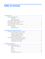 5
5 -
 6
6 -
 7
7 -
8
-
9
-
10
-
11
-
12
-
13
-
14
-
15
-
16
-
17
-
18
-
19
-
20
-
21
-
22
-
23
-
24
-
25
-
26
-
27
-
28
-
29
-
30
-
31
-
32
-
33
-
34
-
35
-
36
-
37
-
38
-
39
-
40
-
41
-
42
-
43
-
44
-
45
-
46
-
47
-
48
-
49
-
50
-
51
-
52
-
53
-
54
-
55
-
56
-
57
-
58
-
59
-
60
-
61
-
62
-
63
-
64
-
65
-
66
-
67
-
68
-
69
-
70
-
71
-
72
-
73
-
74
-
75
-
76
-
77
-
78
-
79
-
80
-
81
-
82
-
83
-
84
-
85
-
86
-
87
-
88
-
89
-
90
-
91
-
92
-
93
-
94
-
95
-
96
-
97
-
98
-
99
-
100
-
101
-
102
-
103
-
104
-
105
-
106
-
107
-
108
-
109
-
110
-
111
-
112
-
113
-
114
-
115
-
116
-
117
-
118
-
119
-
120
-
121
-
122
-
123
-
124
-
125
-
126
-
127
-
128
-
129
-
130
-
131
-
132
-
133
-
134
-
135
-
136
-
137
-
138
-
139
-
140
-
141
-
142
-
143
-
144
-
145
-
146
-
147
-
148
-
149
-
150
-
151
-
152
-
153
-
154
-
155
-
156
-
157
-
158
-
159
-
160
-
161
-
162
-
163
-
164
-
165
-
166
-
167
-
168
-
169
-
170
-
171
-
172
-
173
-
174
-
175
-
176
-
177
-
178
-
179
-
180
-
181
-
182
-
183
-
184
-
185
-
186
-
187
-
188
-
189
-
190
-
191
-
192
-
193
-
194
-
195
-
196
-
197
-
198
-
199
-
200
-
201
-
202
-
203
-
204
-
205
-
206
-
207
-
208
-
209
-
210
-
211
-
212
-
213
-
214
-
215
-
216
-
217
-
218
-
219
-
220
-
221
-
222
-
223
-
224
-
225
-
226
-
227
-
228
-
229
-
230
-
231
-
232
-
233
-
234
-
235
-
236
-
237
-
238
-
239
-
240
-
241
-
242
-
243
-
244
-
245
 |
 |

Maintenance and Service Guide
HP ProDesk 600 G1 Tower
HP ProDesk 600 G1 Small Form Factor