HP ProLiant BL495c HP ProLiant BL495c Server Blade Installation Instructions - Page 2
Connecting to the network, Installing a server blade
 |
View all HP ProLiant BL495c manuals
Add to My Manuals
Save this manual to your list of manuals |
Page 2 highlights
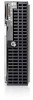
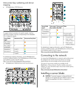
Interconnect bay numbering and device mapping • HP BladeSystem c7000 Enclosure To support network connections for specific signals, install an interconnect module in the bay corresponding to the embedded NIC or mezzanine signals. Server blade signal Flex-10 NIC 1 (embedded) Flex-10 NIC 2 (embedded) Mezzanine 1 Mezzanine 2 Interconnect bay Interconnect bay labels 1 2 3 and 4 5 and 6 7 and 8 For detailed port mapping information, see the HP BladeSystem enclosure installation poster or the HP BladeSystem enclosure setup and installation guide on the HP website (http://www.hp.com/go/bladesystem/documentation). • HP BladeSystem c3000 Enclosure and Tower Enclosure Server blade Interconnect Interconnect Notes signal bay number bay label Flex-10 NIC 1, 1 - 2 (embedded) Mezzanine 1 2 Four port cards connect to bay 2 Mezzanine 2 3,4 • Four port cards • Ports 1 and 3 connect to bay 3 • Ports 2 and 4 connect to bay 4 For detailed port mapping information, see the HP BladeSystem enclosure installation poster or the HP BladeSystem enclosure setup and installation guide on the HP website (http://www.hp.com/go/bladesystem/documentation). Connecting to the network To connect the HP BladeSystem to a network, each enclosure must be configured with network interconnect devices to manage signals between the server blades and the external network. Two types of interconnect modules are available for HP BladeSystem c-Class enclosures: Pass-thru modules and switch modules. For more information about interconnect module options, see the HP website (http://www.hp.com/go/bladesystem/interconnects). Installing a server blade CAUTION: To prevent improper cooling and thermal damage, do not operate the server blade enclosure unless all bays are populated with either a component or a blank.
-
 1
1 -
 2
2 -
 3
3
 |
 |
