HP ProLiant DL185 HP ProLiant DL185 Generation 5 Server Maintenance and Servic
HP ProLiant DL185 - G5 Server Manual
 |
View all HP ProLiant DL185 manuals
Add to My Manuals
Save this manual to your list of manuals |
HP ProLiant DL185 manual content summary:
- HP ProLiant DL185 | HP ProLiant DL185 Generation 5 Server Maintenance and Servic - Page 1
HP ProLiant DL185 Generation 5 Server Maintenance and Service Guide Part number 448688-005 Fifth edition April 2009 - HP ProLiant DL185 | HP ProLiant DL185 Generation 5 Server Maintenance and Servic - Page 2
is subject to change without notice. The only warranties for HP products and services are set forth in the express warranty statements accompanying such products and services. Nothing herein should be construed as constituting an additional warranty. HP shall not be liable for technical or editorial - HP ProLiant DL185 | HP ProLiant DL185 Generation 5 Server Maintenance and Servic - Page 3
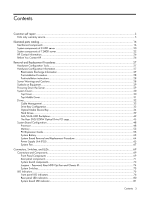
Contents Customer self repair ...5 Parts only warranty service...5 Illustrated parts catalog ...16 Mechanical components ...16 System components of 8 HDD server ...20 System components of 12HDD server ...22 HP Contact Information...26 Before You Contact HP ...26 Removal and Replacement Procedures - HP ProLiant DL185 | HP ProLiant DL185 Generation 5 Server Maintenance and Servic - Page 4
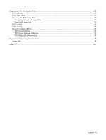
BIOS Setup Utility ...82 Navigating through the Setup Utility ...83 Setup Utility Menu Bar ...85 BIOS Update...93 Clear CMOS...94 Power-On Self-Test (POST)...94 POST Error Indicators ...94 POST Errors Message Definition...95 POST Related Troubleshooting ...97 Physical and Operating Specifications - HP ProLiant DL185 | HP ProLiant DL185 Generation 5 Server Maintenance and Servic - Page 5
warranty service designated for your product. NOTE: Some HP parts are not designed for customer self repair. In order to satisfy the customer warranty, HP requires that an authorized service can call the HP Technical Support Center and a technician will help you over the telephone. HP specifies in - HP ProLiant DL185 | HP ProLiant DL185 Generation 5 Server Maintenance and Servic - Page 6
pièce défectueuse, HP se réserve le droit de vous facturer les coûts de remplacement. Dans le cas d'une pièce CSR, HP supporte l'ensemble des frais le site Web HP (http://www.hp.com/go/selfrepair). Service de garantie "pièces seules" Votre garantie limitée HP peut inclure un service de garantie "pi - HP ProLiant DL185 | HP ProLiant DL185 Generation 5 Server Maintenance and Servic - Page 7
due categorie di parti CSR: • Obbligatorie - Parti che devono essere necessariamente riparate dal cliente. Se il cliente ne affida la riparazione ad HP, deve sostenere le spese di spedizione e di manodopera per il servizio. • Opzionali - Parti la cui riparazione da parte del cliente è facoltativa - HP ProLiant DL185 | HP ProLiant DL185 Generation 5 Server Maintenance and Servic - Page 8
können Sie das HP technische Support Center anrufen und Warranty Service (Garantieservice ausschließlich für Teile) Ihre HP Garantie umfasst möglicherweise einen Parts-only Warranty Service (Garantieservice ausschließlich für Teile). Gemäß den Bestimmungen des Parts-only Warranty Service stellt HP - HP ProLiant DL185 | HP ProLiant DL185 Generation 5 Server Maintenance and Servic - Page 9
componentes CSR se clasifican en dos categorías: • Obligatorio: componentes para los que la reparación por parte del usuario es obligatoria. Si solicita a HP que realice la sustitución de estos componentes, tendrá que hacerse cargo de los gastos de desplazamiento y de mano de obra de dicho servicio - HP ProLiant DL185 | HP ProLiant DL185 Generation 5 Server Maintenance and Servic - Page 10
onderdelen worden CSR-onderdelen (Customer Self Repair) genoemd. Als HP (of een HP Service Partner) bij de diagnose vaststelt dat de reparatie kan gebracht, afhankelijk van het type garantieservice voor het product. OPMERKING: Sommige HP onderdelen zijn niet ontwikkeld voor reparatie door de klant - HP ProLiant DL185 | HP ProLiant DL185 Generation 5 Server Maintenance and Servic - Page 11
diretamente ao cliente. Existem duas categorias de peças CSR: • Obrigatória - Peças cujo reparo feito pelo cliente é obrigatório. Se desejar que a HP substitua essas peças, serão cobradas as despesas de transporte e mão-de-obra do serviço. • Opcional - Peças cujo reparo feito pelo cliente é opcional - HP ProLiant DL185 | HP ProLiant DL185 Generation 5 Server Maintenance and Servic - Page 12
Contents 12 - HP ProLiant DL185 | HP ProLiant DL185 Generation 5 Server Maintenance and Servic - Page 13
Contents 13 - HP ProLiant DL185 | HP ProLiant DL185 Generation 5 Server Maintenance and Servic - Page 14
Contents 14 - HP ProLiant DL185 | HP ProLiant DL185 Generation 5 Server Maintenance and Servic - Page 15
Contents 15 - HP ProLiant DL185 | HP ProLiant DL185 Generation 5 Server Maintenance and Servic - Page 16
Description 1 Top cover 2 Rail kit 3 Hard drive cage for 8 HDD model 4 Hardware/Plastics Kit a. Hard drive dummy (fixed) b. Hard drive dummy (removable) c. Power for 12 HDD model 6 Top middle cover 7 Power supply cage Spare part number 454347-001 454367-001 454365-001 454348-001 - HP ProLiant DL185 | HP ProLiant DL185 Generation 5 Server Maintenance and Servic - Page 17
not be additional charges, depending on the type of warranty service designated for your product. 3No-Some HP parts are not designed for customer self repair. In order to satisfy the customer warranty, HP requires that an authorized service provider replace the part. These parts are identified as - HP ProLiant DL185 | HP ProLiant DL185 Generation 5 Server Maintenance and Servic - Page 18
garantieservice voor het product. 3No: Nee-Sommige HP onderdelen zijn niet Service Partner worden vervangen. Deze onderdelen worden in de geïllustreerde onderdelencatalogus aangemerkt met "Nee". 1Mandatory: Obrigatória-Peças cujo reparo feito pelo cliente é obrigatório. Se desejar que a HP - HP ProLiant DL185 | HP ProLiant DL185 Generation 5 Server Maintenance and Servic - Page 19
Contents 19 - HP ProLiant DL185 | HP ProLiant DL185 Generation 5 Server Maintenance and Servic - Page 20
server Table 2 System Components Spare Parts List Item Description 1 System Fan 2 Backplane Eight bays SAS/SATA Hard Drive 3 Cable Assy, USB, Internal (optional) 4 Cable, SAS/SATA 5 Memory Processors ,Opteron Series IC, uP, Opteron 2346HE, 1.8 GHz, 68W Spare Part Number 454350-001 454349 - HP ProLiant DL185 | HP ProLiant DL185 Generation 5 Server Maintenance and Servic - Page 21
Table 2 System Components Spare Parts List Item Description IC, uP, Opteron 2352, 2.1 GHz, 95W IC, uP, Opteron 2354, 2.2 GHz, 95W 10 Power Backplane Assy. 11 Low Profile PCIe Riser Cards 12 FH/FL PCIe Riser Card 13 Rear DVD Cage Assy Spare Part Number 448033-001 448034-001 448035-001 451810 - HP ProLiant DL185 | HP ProLiant DL185 Generation 5 Server Maintenance and Servic - Page 22
server Table 3 System Components Spare Parts List Item Description 1 System Fan 2 Backplane 12 bays SAS/SATA Hard Drive 3 Cable Assy, USB, Internal (optional) 4 Cable, SAS/SATA 5 Memory 5300,512Mx4,RoHS 6 Processors ,Opteron Series Spare Part Number 454350-001 460001-001 454366-001 - HP ProLiant DL185 | HP ProLiant DL185 Generation 5 Server Maintenance and Servic - Page 23
not be additional charges, depending on the type of warranty service designated for your product. 3No-Some HP parts are not designed for customer self repair. In order to satisfy the customer warranty, HP requires that an authorized service provider replace the part. These parts are identified as - HP ProLiant DL185 | HP ProLiant DL185 Generation 5 Server Maintenance and Servic - Page 24
optional ist. Diese Teile sind auch für Customer Self Repair ausgelegt. Wenn Sie jedoch den Austausch dieser Teile von HP vornehmen lassen möchten, können bei diesem Service je nach den für Ihr Produkt vorgesehenen Garantiebedingungen zusätzliche Kosten anfallen. 3No: Kein-Einige Teile sind nicht - HP ProLiant DL185 | HP ProLiant DL185 Generation 5 Server Maintenance and Servic - Page 25
type garantieservice voor het product. 3No: Nee-Sommige HP onderdelen zijn niet Service Partner worden vervangen. Deze onderdelen worden in de geïllustreerde onderdelencatalogus aangemerkt met "Nee". 1Mandatory: Obrigatória-Peças cujo reparo feito pelo cliente é obrigatório. Se desejar que a HP - HP ProLiant DL185 | HP ProLiant DL185 Generation 5 Server Maintenance and Servic - Page 26
refer to the HP website at http://www.hp.com/. For HP technical support: • In North America: ○ Call 1-800-HP-INVENT (1-800-474-6836). This service is available 24 hours you call HP: • Technical support registration number (if applicable) • Product serial number • Product model name and number • - HP ProLiant DL185 | HP ProLiant DL185 Generation 5 Server Maintenance and Servic - Page 27
HP ProLiant DL185 G5 server. Review the specifications of a new component before installing it to make sure it is compatible with the server. When you integrate new components into the system, record its model and serial number HP ProLiant DL185 G5 Server Support • Transport products in static-safe - HP ProLiant DL185 | HP ProLiant DL185 Generation 5 Server Maintenance and Servic - Page 28
the described step-by-step instructions. 2. Reinstall the peripherals, system cables, rear cage, and air baffle you have removed. 3. Reinstall the top middle cover. 4. Reinstall the top cover. 5. Reinstall server into rack. 6. Connect all external cables and the AC power cord to the system. 7. Press - HP ProLiant DL185 | HP ProLiant DL185 Generation 5 Server Maintenance and Servic - Page 29
for manual material handling. These symbols, on power supplies or systems, indicate that the equipment is supplied by multiple sources of power. WARNING: To reduce the risk of injury from electric shock, remove all power cords to completely disconnect power from the system. Powering Down the Server - HP ProLiant DL185 | HP ProLiant DL185 Generation 5 Server Maintenance and Servic - Page 30
power from the system, disconnect all power cords from the server. To power down the server: 1. Shut down server as directed by the operating system documentation. 2. Press the power can remove or replace a server component. The middle cover needs to be removed to service the SAS/SATA backplane board - HP ProLiant DL185 | HP ProLiant DL185 Generation 5 Server Maintenance and Servic - Page 31
2. Once the cover is attached to the chassis, tighten the captive screw on the rear panel with a T-15 screwdriver. Figure 2 Reinstalling the Top Cover Top Middle Cover To remove the top middle cover: 1. Remove the top cover. 2. Remove the screws (one on each side of the chassis and those on the top - HP ProLiant DL185 | HP ProLiant DL185 Generation 5 Server Maintenance and Servic - Page 32
Reinstalling the Top Middle Cover Drives The server supports 9 to 12 drive bays --- 8 jam cables on top of expansion cards or memory modules. Printed circuit cards are not designed to , power supply, or system cover in order not to push cables down into the chassis. Removing power supply power cables - HP ProLiant DL185 | HP ProLiant DL185 Generation 5 Server Maintenance and Servic - Page 33
Figure 5 unplugging power cables Drive Bay Configuration Figure 6 System Drive Bays / 8 HDD model Item Description 1 Optical drive bay 2 3.5 Inch Hard Disk Drive Bays (8 ) The HDD bays support both non-hot-plug and hot-plug SATA drives, as well as hot-plug SAS drives. Contents 33 - HP ProLiant DL185 | HP ProLiant DL185 Generation 5 Server Maintenance and Servic - Page 34
Drive Bays / 12 HDD model Item Description 1 3.5 Inch Hard Disk Drive Bays (12 ) The HDD bays support both non-hot-plug and hot-plug SATA drives, as well as hot-plug SAS drives. Optical Media Device Bay The optical media device bay of servers with 8 HDD supports the installation of a 127mm DVD - HP ProLiant DL185 | HP ProLiant DL185 Generation 5 Server Maintenance and Servic - Page 35
Figure 8 Removing the Optical Drive Carrier To remove the bezel blank from the optical drive carrier: 1. Press in the four tabs (two on the top and two on the bottom) to release the bezel blank from the carrier. 2. Pull the bezel blank out of the carrier. CAUTION: Do not discard the bezel blank. If - HP ProLiant DL185 | HP ProLiant DL185 Generation 5 Server Maintenance and Servic - Page 36
into the chassis. 4. Secure the optical drive to the chassis with the screw. Figure 11 Installing the optical drive assembly 5. Connect the IDE data and power cables to their corresponding connectors on the optical drive. Contents 36 - HP ProLiant DL185 | HP ProLiant DL185 Generation 5 Server Maintenance and Servic - Page 37
Figure 12 Connecting the Cables To remove the optical drive: 1. Remove the screw that secures the optical drive carrier to the chassis. 2. Push the carrier toward the front of the unit. 3. Pull the carrier with optical drive out of the chassis. Figure 13 Removing the Optical Drive To remove the - HP ProLiant DL185 | HP ProLiant DL185 Generation 5 Server Maintenance and Servic - Page 38
Figure 14 Removing the Optical Drive from its Carrier IMPORTANT: If you remove an optical drive without plans of installing a new one, you must reinstall the blank to maintain proper system airflow. Contents 38 - HP ProLiant DL185 | HP ProLiant DL185 Generation 5 Server Maintenance and Servic - Page 39
are labeled from Device 1 to Device 8, from left to right, top to bottom, when viewed from the front of the server. Figure 15 Hard Drive Bays Configuration / 8 HDD model Item 1 2 3 4 5 6 7 8 Description 1st SAS/SATA Hard Drive 2nd SAS/SATA Hard Drive 3rd SAS/SATA Hard Drive 4th SAS/SATA Hard Drive - HP ProLiant DL185 | HP ProLiant DL185 Generation 5 Server Maintenance and Servic - Page 40
Device 1 to Device 12, from left to right, top to bottom, when viewed from the front of the server. Figure 16 Hard Drive Bays Configuration / 12 HDD model Item 1 2 3 4 5 6 7 8 9 10 11 12 Description 1st SAS/SATA Hard Drive 2nd SAS/SATA Hard Drive 3rd SAS/SATA Hard Drive 4th SAS/SATA Hard - HP ProLiant DL185 | HP ProLiant DL185 Generation 5 Server Maintenance and Servic - Page 41
hard disk carrier button to release the ejector lever. 2. Use the HDD carrier latch to pull the drive out of the cage. Make sure to support the drive when pulling it out of the cage. 3. Pull the hard drive assembly out of the drive bay. Contents 41 - HP ProLiant DL185 | HP ProLiant DL185 Generation 5 Server Maintenance and Servic - Page 42
Figure 19 Removing the Hard Drive SAS/SATA HDD Backplane Figure 20 Backplane Connectors of server with 8 HDD (component side) Item Description 1 Hard drive connectors 2 Screw holes 3 LED indicators Contents 42 - HP ProLiant DL185 | HP ProLiant DL185 Generation 5 Server Maintenance and Servic - Page 43
21 Backplane Connectors of server with 12 HDD (component side) Item Description 1 Hard drive connectors 2 Screw holes 3 LED indicators Figure 22 Backplane Connectors of server with 8 HDD (solder side) Item Description 1 SAS/SATA cable connectors 2 10-pin power connector Contents 43 - HP ProLiant DL185 | HP ProLiant DL185 Generation 5 Server Maintenance and Servic - Page 44
HDD (solder side) Item 1 2 3 4 Description 10-pin power connector LED signal cable connect to rear 2 HDD option SAS connector Cable connectors for rear 2 HDD option WARNING: Ensure that the system is powered off and all power sources have been disconnected from the server. Voltages are present at - HP ProLiant DL185 | HP ProLiant DL185 Generation 5 Server Maintenance and Servic - Page 45
/CDRW Optical Drive PCI cage: 1. Remove the screw that secures the optical drive carrier to the rear DVD/CDRW optical drive PCI cage using a T-10 driver. (step 1 in figure 26) 2. Pull the optical drive carrier out of the cage. (step 2 in figure 26) Contents 45 - HP ProLiant DL185 | HP ProLiant DL185 Generation 5 Server Maintenance and Servic - Page 46
1 in figure 27) 4. Secure the optical drive to the carrier with the provided mounting screws. (step 2 in figure 27) 5. Connect the IDE data and power cables to their corresponding connectors on the optical drive. To Install the Rear DVD/CDRW Optical Drive PCI cage: Figure 27 Assembling the optical - HP ProLiant DL185 | HP ProLiant DL185 Generation 5 Server Maintenance and Servic - Page 47
Figure 28 Installing the optical drive assembly 7. Reinstall any PCI cards from the old rear cage. 8. Connect the IDE data and power cables to their corresponding connectors on the optical drive. Figure 29 Installing the rear DVD/CDRW optical drive PCI cage 9. Install the rear DVD/CDRW - HP ProLiant DL185 | HP ProLiant DL185 Generation 5 Server Maintenance and Servic - Page 48
System Board Configuration Processor HP ProLiant DL185 G5 Server supports dual-processor operation. If a single processor is installed, then use socket 0. When two processors are used, the server supports boot functions through the processor installed in processor socket 0. However, if processor 0 - HP ProLiant DL185 | HP ProLiant DL185 Generation 5 Server Maintenance and Servic - Page 49
Figure 31 Removing the Air Baffle To remove the heat sink: 1. Loosen the two mounting pins. 2. Lift the heat sink away from the system board. CAUTION: Place heat sink down in an upright position with the thermal patch facing upward. Do not let the thermal patch touch the work surface. Figure 32 - HP ProLiant DL185 | HP ProLiant DL185 Generation 5 Server Maintenance and Servic - Page 50
no particles or dust contaminants are evident. 2. Apply the thermal grease compound to the CPU contact surface. CAUTION: HP recommends using Shin-Etsu X-23-7783D thermal grease compound for your ProLiant server. 3. Apply all the grease to the top of the processor in one of the following patterns to - HP ProLiant DL185 | HP ProLiant DL185 Generation 5 Server Maintenance and Servic - Page 51
Figure 34 The top of the processor CAUTION: Never touch the bottom of the processor; any contaminant could prevent the mounting pads from making contact with the socket. CAUTION: Applying too much grease creates a gap between the contact surfaces, significantly reducing the ability of the heat sink - HP ProLiant DL185 | HP ProLiant DL185 Generation 5 Server Maintenance and Servic - Page 52
Figure 35 Installing the processor CAUTION: To prevent overheating or a possible system crash, use only a heat sink model specified for the HP ProLiant DL185 G5 server. To install the heat sink: 1. Properly align the heat sink mounting pins to the system board mounting holes. 2. Tighten the - HP ProLiant DL185 | HP ProLiant DL185 Generation 5 Server Maintenance and Servic - Page 53
Figure 37 Installing the air baffle Memory HP ProLiant DL185 G5 server has 8 DIMM slots that support up to 32 GB maximum system memory (4 GB in each of the eight DIMM slots). You must adhere to the following guidelines when adding or replacing memory modules: • For 2P system, both physical - HP ProLiant DL185 | HP ProLiant DL185 Generation 5 Server Maintenance and Servic - Page 54
module upward to remove it from the slot. Figure 39 Removing a memory module CAUTION: Place the memory module on a static-dissipating work surface or inside of an anti-static bag. To install a memory module: 1. Align the notch on the bottom edge of the module with the keyed surface of the DIMM - HP ProLiant DL185 | HP ProLiant DL185 Generation 5 Server Maintenance and Servic - Page 55
structured to ensure proper installation. If you insert a memory module but it does not fit easily into the Item Component Designator 1 J19 2 J33 Component PCI slot PCI slot Function Supports a PCIe Riser Card Supports a PCIe Riser Card PCI Riser card Expansion Slots The two PCI Express - HP ProLiant DL185 | HP ProLiant DL185 Generation 5 Server Maintenance and Servic - Page 56
Figure 42 Installing the Dual-slot Riser card • Dual-Slot PCIe riser card (x8 link with x8 slot) Figure 43 PCIe Riser card connector location • PCIe riser card (x4 link with x8 slot) PCI cage To remove the PCI cage: NOTE: Disconnect all cables connecting an existing expansion board to the system - HP ProLiant DL185 | HP ProLiant DL185 Generation 5 Server Maintenance and Servic - Page 57
Figure 44 Removing the PCI cage To install the PCI cage: 1. Align the PCI cage to the system board expansion slot, and then press it down to ensure full connection to the system board. Figure 45 Installing the PCI cage Contents 57 - HP ProLiant DL185 | HP ProLiant DL185 Generation 5 Server Maintenance and Servic - Page 58
to secure the PCI cage to the chassis. Installing PCIe/PCI-X Riser Board The system supports up to two riser boards at a time. Use only HP supported expansion boards that meet the following specifications: • Compliance ○ PCI Express x4 or x8 ○ PCI-X (available only when the optional PCI-X riser - HP ProLiant DL185 | HP ProLiant DL185 Generation 5 Server Maintenance and Servic - Page 59
To remove the PCIe riser card: 1. Remove the two screws securing the riser card to the PCI cage. 2. Push the riser card down and away from the PCI cage. Figure 47 Removing the PCIe Riser card Figure 48 Removing the PCIe Riser card To install the PCIe riser card: 1. Align the two riser card slots to - HP ProLiant DL185 | HP ProLiant DL185 Generation 5 Server Maintenance and Servic - Page 60
Figure 49 Installing the PCIe Riser card Figure 50 Installing the PCIe Riser card To remove the slot cover: 1. Remove the screw(s) that secure(s) the slot cover(s) to the chassis. 2. Remove the slot cover(s) on the PCI cage. CAUTION: Do not discard the slot cover. If the expansion board is removed - HP ProLiant DL185 | HP ProLiant DL185 Generation 5 Server Maintenance and Servic - Page 61
Figure 51 Removing the slot cover (1) Figure 52 Removing the slot cover (2) To install the PCI card: 1. Slide the expansion board into the slot, aligning the board with its matching connector. Firmly press the board to seat it properly on the slot. 2. Tighten the screw that secures the card to the - HP ProLiant DL185 | HP ProLiant DL185 Generation 5 Server Maintenance and Servic - Page 62
Figure 53 Installing the PCI card (1) Figure 54 Installing the PCI card (2) Contents 62 - HP ProLiant DL185 | HP ProLiant DL185 Generation 5 Server Maintenance and Servic - Page 63
System Battery The server uses nonvolatile memory that requires a battery to retain system information when power is removed. This instructions. CAUTION: Loss of BIOS settings occurs when the battery is removed. You must reconfigure BIOS settings whenever you replace the battery. NOTE: If the server - HP ProLiant DL185 | HP ProLiant DL185 Generation 5 Server Maintenance and Servic - Page 64
Figure 56 Replacing the battery System Board Removal and Replacement Procedure To remove the system board: 1. Remove the top cover. 2. Remove the air baffle. 3. Disconnect all cables connected to the system board. 4. Loosen the nine screws that secure the system board to the chassis. 5. Slide the - HP ProLiant DL185 | HP ProLiant DL185 Generation 5 Server Maintenance and Servic - Page 65
the risk of personal injury from electric shock hazards and/or damage to the equipment. • Installation of power supply units should be referred to individuals who are qualified to service server systems and are trained to deal with equipment capable of generating hazardous energy levels. • DO NOT - HP ProLiant DL185 | HP ProLiant DL185 Generation 5 Server Maintenance and Servic - Page 66
the blue colored handle. 3. Slide the power supply out of the power supply bay. Figure 60 Removing the power supply To replace the power supply: 1. Align the power supply cage connector with the open slot of power supply, and slide the power supply into the power supply bay until it snaps into place - HP ProLiant DL185 | HP ProLiant DL185 Generation 5 Server Maintenance and Servic - Page 67
system board P19 on the system board System fans 1 to 3 are for the memory modules and processors, while system fan 4 is for the PCI slots and system chipsets. A new system fan can be installed to allow the server to operate properly in case a default system fan becomes defective. To remove the - HP ProLiant DL185 | HP ProLiant DL185 Generation 5 Server Maintenance and Servic - Page 68
Figure 63 Removing the system fan To replace the system fan: 1. Squeeze the release tab. 2. Insert the system fan into the fan bracket. 3. Secure the cable using the cable clip located on the chassis' partition wall. 4. Connect the fan cable to its corresponding board connector. Figure 64 Installing - HP ProLiant DL185 | HP ProLiant DL185 Generation 5 Server Maintenance and Servic - Page 69
the front panel, rear panel, system board and hard drives of the HP ProLiant DL185 G5 server. Connectors and Components Front Panel Components Figure 65 Front Panel Components for 8 HDD Server Item 1 2 3 4 5 6 7 8 9 10 Description Two Front USB 2.0 Ports Optical Disc Drive (optional) Optical Disc - HP ProLiant DL185 | HP ProLiant DL185 Generation 5 Server Maintenance and Servic - Page 70
Figure 66 Front Panel Components for 12 HDD Server Item 1 2 3 4 5 6 7 Description Two Front USB 2.0 Ports UID LED button Power LED button Rack thumbscrews Drive Activity LED Drive Online/Error LED Hard Disk Drive (HDD) Bay Contents 70 - HP ProLiant DL185 | HP ProLiant DL185 Generation 5 Server Maintenance and Servic - Page 71
Rear panel components Figure 67 Rear panel components for PCI Figure 68 Rear panel components for HDD Contents 71 - HP ProLiant DL185 | HP ProLiant DL185 Generation 5 Server Maintenance and Servic - Page 72
Figure 69 Rear panel components for ODD Item 1 2 3 4a 4b 5a 5b 6 7 8 9 10 11 12 13 14 Description Power supply cable socket T10/T15 Wrench Thumbscrew for top cover Low-profile PCI expansion card slot Optical disc drive (ODD) bay PCI card slot cover - HP ProLiant DL185 | HP ProLiant DL185 Generation 5 Server Maintenance and Servic - Page 73
70 System board components Item 1 2 3 4 5 6 7 8 9 10 11 Designator Description J22 Top: PS/2 mouse port Bottom: PS/2 keyboard port J16 Dual LAN port CN21 Top: X8 slot J33 PCIe X16 slot MT9 Redundant Power Supply Management Interface Connector J21 Internal USB connector Contents 73 - HP ProLiant DL185 | HP ProLiant DL185 Generation 5 Server Maintenance and Servic - Page 74
Item 12 13 14 15 16 17 18 19 20 21 22 23 24 25 26 27 28 29 30 Designator Description P141 Power for rear HDD backplane P20 Password jumper J20 PSMI J36 Front panel sensor connector P10 Front panel port P19 5-pin system fan header P25 IDE - HP ProLiant DL185 | HP ProLiant DL185 Generation 5 Server Maintenance and Servic - Page 75
) to manually force the server to issue a Non-Maskable Interrupt (NMI). This will perform a memory dump-writing the contents in the server's CPU registers and system memory to a network server or to diskettes. This memory dump can later be analyzed to determine the cause of the problem. By default - HP ProLiant DL185 | HP ProLiant DL185 Generation 5 Server Maintenance and Servic - Page 76
indicators allow constant monitoring of basic system functions while the server is operating. Optical drive activity LED indicator The optical drive the drive is reading media. Figure 72 Optical drive activity LED indicator of server with 8 HDD Activity states for the optical drive are as follows: • - HP ProLiant DL185 | HP ProLiant DL185 Generation 5 Server Maintenance and Servic - Page 77
the front panel. Figure 73 Power LED Indicator Location Table 5 Power LED indicator status Component Power LED indicator Status Steady green Steady Amber Off Description The server is operating normally. The server is system off or in hibernation with A/C power. The server is system off without - HP ProLiant DL185 | HP ProLiant DL185 Generation 5 Server Maintenance and Servic - Page 78
6 Hard drive activity LED indicator status Item 1 LED indicator Drive Online/Error LED indicator Status Description Forced off (override drive • The drive is not a member activity output) of any RAID volumes; or the drive is configured but is in a replacement or failed state for at least - HP ProLiant DL185 | HP ProLiant DL185 Generation 5 Server Maintenance and Servic - Page 79
LED indicator status Item 2 LED indicator Status Description Flashing green during a • The drive is currently drive activity (if command performing an I/O activity. is outstanding continually • The drive is a member of a the indicator is forced to RAID volume. flash at 4 Hz 50% duty cycle - HP ProLiant DL185 | HP ProLiant DL185 Generation 5 Server Maintenance and Servic - Page 80
states Item Component Status 1 LAN network speed LED Steady green indicator Steady amber Off 2 LAN activity status LED Flashing green indicator Off Description The LAN connection is using a GbE link. The LAN connection is using 10Mbps/100 Mbps link. No connection. Ongoing network data - HP ProLiant DL185 | HP ProLiant DL185 Generation 5 Server Maintenance and Servic - Page 81
system board contains internal status LED indicators for use during troubleshooting operations. Figure 76 System board LED indicator Table 8 System board LED indicator Item Component 1 Management processor indicator Status Blinking Description The management processor is running Contents 81 - HP ProLiant DL185 | HP ProLiant DL185 Generation 5 Server Maintenance and Servic - Page 82
Utilities This chapter provides an overview of the Power-On Self-Test (POST), the POST error messages, and BIOS, SAS and SATA setup utilities. BIOS Software The server uses BIOS to boot up the system. BIOS software is a ROM-based firmware that allows reliability, manageability, and connectivity - HP ProLiant DL185 | HP ProLiant DL185 Generation 5 Server Maintenance and Servic - Page 83
field help panel-Item Specific Help panel. This panel displays the help text for the currently selected field. It updates as you move the General Help window describes other Setup navigation keys that are not displayed on the legend bar. To change BIOS Setup Utility screen colours. Discard any - HP ProLiant DL185 | HP ProLiant DL185 Generation 5 Server Maintenance and Servic - Page 84
Navigation Keys Key Esc Figure 77 Setup Utility General Help screen Function If you press this key: • On one of the primary menu screens, the Exit menu displays. • On a submenu screen, the - HP ProLiant DL185 | HP ProLiant DL185 Generation 5 Server Maintenance and Servic - Page 85
Setup Utility Menu Bar The BIOS Setup Utility provides a menu bar with the menu selections. The menu bar choices are described in the topics below. Main Menu Figure 78 Main menu of the BIOS Setup Utility Contents 85 - HP ProLiant DL185 | HP ProLiant DL185 Generation 5 Server Maintenance and Servic - Page 86
and version. • View CPU type / CPU speed. • View System memory size. • View System serial number. • View MAC address for the embedded NIC. • Set Server Asset Tag. • Set system time and date. • Set boot features: ○ Enable or Disable the BIOS summary display. ○ Turn on or off Bootup Num-Lock. ○ Set - HP ProLiant DL185 | HP ProLiant DL185 Generation 5 Server Maintenance and Servic - Page 87
menu of the BIOS Setup Utility 1 WARNING: Incorrect settings may cause the server to malfunction. chipset SCH4307. • S-ATA Configuration --- Configure Server Works HT 1000 S-ATA. • ACPI Configuration • IPMI Configuration --- IPMI Configuration including server monitoring and event log. • Remote - HP ProLiant DL185 | HP ProLiant DL185 Generation 5 Server Maintenance and Servic - Page 88
Figure 81 IPMI submenu of the BIOS Setup Utility • SEL Configuration --- Configuration of the BMC System Event Log. • Serial Port Configuration --- Select to configure system serial ports. • LAN Configuration --- Select for LAN configuration. • - HP ProLiant DL185 | HP ProLiant DL185 Generation 5 Server Maintenance and Servic - Page 89
menu of the BIOS Setup Utility Use this menu to configure the boot priority. • Boot Device Priority --- Use this screen to specify the order in which the system checks for a boot device. • Embedded NIC Port 1 PXE --- Use this screen to configure the embedded NIC Port 1 PXE boot option. The default - HP ProLiant DL185 | HP ProLiant DL185 Generation 5 Server Maintenance and Servic - Page 90
Security Menu Figure 83 Security menu of the BIOS Setup Utility 1 Contents 90 - HP ProLiant DL185 | HP ProLiant DL185 Generation 5 Server Maintenance and Servic - Page 91
Figure 84 Security menu of the BIOS Setup Utility 2 Use this menu to configure the following items: Contents 91 - HP ProLiant DL185 | HP ProLiant DL185 Generation 5 Server Maintenance and Servic - Page 92
Setup automatically sets the password check to Setup. Figure 85 Security menu of the BIOS Setup Utility 3 When administer password is installed, use this menu to check password: • Setup --- Check password while invoking setup. • Always --- Check password while invoking setup as well as on each boot - HP ProLiant DL185 | HP ProLiant DL185 Generation 5 Server Maintenance and Servic - Page 93
below to update BIOS: 1. Download the Smart Component (SPxxxxx.exe) to a directory on your hard drive. 2. Execute (SPxxxxx.exe) and followed with direction to complete the steps. "ProLiant Flash Update" interface will appear. 3. Select items which need to execute: ○ Create a bootable ROMPaq diskette - HP ProLiant DL185 | HP ProLiant DL185 Generation 5 Server Maintenance and Servic - Page 94
Flashing Capabilities 4. Reboot DL185 G5 Server with one of the above bootable devices and make sure the BIOS setting allows booting from the USB disk. 5. Follow the on-screen instructions to finish the flashing of the BIOS. Clear CMOS You may need to clear the Setup configuration values (CMOS) if - HP ProLiant DL185 | HP ProLiant DL185 Generation 5 Server Maintenance and Servic - Page 95
POST error messages with corresponding troubleshooting recommendation. HP recommends that you correct the error, even if the server appears to boot successfully. Table 10 POST Error Messages Error-Code 000 003 004 005 012 048 04D 04E Error Message Description / Corrective Action Timer Error - HP ProLiant DL185 | HP ProLiant DL185 Generation 5 Server Maintenance and Servic - Page 96
Uncorrectable memory error Microcode Error Checking NVRAM Update Failed Operating system not found Description / Corrective after displaying this message. If the problem persists, contact HP Customer Support. BIOS could not find or load the CPU Microcode Update to the CPU. The message is - HP ProLiant DL185 | HP ProLiant DL185 Generation 5 Server Maintenance and Servic - Page 97
Log full Description / Corrective BIOS SETUP UTILITY and then Clean the System Event Log. POST Related Troubleshooting power cables should be firmly plugged in. • The power outlet to the server should be connected and works correctly. • The server processor. • All memory modules are properly - HP ProLiant DL185 | HP ProLiant DL185 Generation 5 Server Maintenance and Servic - Page 98
the HP ProLiant DL185 G5 server. Specifications include: System Unit Table 11 Hardware Specifications Item Processor socket Processor support Chipset Hardware monitoring device Gigabit Ethernet controller IDE controllers Embedded video controller I/O subsystem Memory Default media storage Optional - HP ProLiant DL185 | HP ProLiant DL185 Generation 5 Server Maintenance and Servic - Page 99
Table 11 Hardware Specifications Item Power Supply unit (PSU) Thermal solution Table 12 Physical Dimensions Item System board platform System board dimension Server dimensions Rack Server weight Table 13 Environmental Specifications Item Temperature: Operating Non-operating Storage Wet-bulb - HP ProLiant DL185 | HP ProLiant DL185 Generation 5 Server Maintenance and Servic - Page 100
input voltage Normal line voltage Line frequency Rated input current BTU rating Power supply output power: Rated steady state power Maximum peak power Temperature range: Operating Shipping Relative humidity: Operating Non-operating Description 40.5 mm x 86.4 mm x 190.5 mm 1.1 kg 90 VAC to 264 VAC - HP ProLiant DL185 | HP ProLiant DL185 Generation 5 Server Maintenance and Servic - Page 101
number, 16 hardware configuration hard drives, 39 memory, 53 optical media drive, 34 PCI expansion cards, 55 power supply unit, 65 processor, 48 references, 27 system battery, 63 system fan, 67 top cover, 30 hardware configuration tools, 27 hardware specifications chipset, 98 default media storage - HP ProLiant DL185 | HP ProLiant DL185 Generation 5 Server Maintenance and Servic - Page 102
power/system health, 77 system board LED, 81 M mechanical parts illustrated, 16 memory module spare part number, 22 memory module spare part number, 20 memory modules guidelines for installation, 53 installing, 54 module orientation, 55 removing, 54 O onboard controllers LAN, 98 storage controller - HP ProLiant DL185 | HP ProLiant DL185 Generation 5 Server Maintenance and Servic - Page 103
card XIV spare part number, 21, 23 S server dimensions rack, 99 server warnings and cautions, 28 Setup Utility menu bar advanced menu, 87 boot menu, 89 exit menu, 93 main menu, 85 security menu, 90 slot cover removing, 60 specifications physical and operating, 98 storage controller, 98 symbols on
-
 1
1 -
 2
2 -
 3
3 -
 4
4 -
 5
5 -
 6
6 -
 7
7 -
8
-
9
-
10
-
11
-
12
-
13
-
14
-
15
-
16
-
17
-
18
-
19
-
20
-
21
-
22
-
23
-
24
-
25
-
26
-
27
-
28
-
29
-
30
-
31
-
32
-
33
-
34
-
35
-
36
-
37
-
38
-
39
-
40
-
41
-
42
-
43
-
44
-
45
-
46
-
47
-
48
-
49
-
50
-
51
-
52
-
53
-
54
-
55
-
56
-
57
-
58
-
59
-
60
-
61
-
62
-
63
-
64
-
65
-
66
-
67
-
68
-
69
-
70
-
71
-
72
-
73
-
74
-
75
-
76
-
77
-
78
-
79
-
80
-
81
-
82
-
83
-
84
-
85
-
86
-
87
-
88
-
89
-
90
-
91
-
92
-
93
-
94
-
95
-
96
-
97
-
98
-
99
-
100
-
101
-
102
-
103
 |
 |

HP ProLiant DL185 Generation 5 Server
Maintenance and Service Guide
Part number 448688-005
Fifth edition April 2009