HP ProLiant SL390s HP ProLiant SL390s G7 1U half width Server Installation She
HP ProLiant SL390s - G7 Server Manual
 |
View all HP ProLiant SL390s manuals
Add to My Manuals
Save this manual to your list of manuals |
HP ProLiant SL390s manual content summary:
- HP ProLiant SL390s | HP ProLiant SL390s G7 1U half width Server Installation She - Page 1
and detailed procedures relating to installation of options, refer to any installation instructions that came with the option, as well as the HP ProLiant SL390s G7 1U half width Server Maintenance and Service Guide. • For safety information, regulatory notices, and detailed procedures related to the - HP ProLiant SL390s | HP ProLiant SL390s G7 1U half width Server Installation She - Page 2
Sockets Installing the Processor The HP ProLiant SL390s server supports Intel Nehalem and Westmere tool and instructions on how to use the tool. It is important to follow the instructions to prevent insert it again. 3. Install the BBWC into the tray and slide it in the direction of the arrow
-
 1
1 -
 2
2
 |
 |
HP ProLiant SL390s G7 1U
half width Server
Installation Sheet
First edition (June 2010)
Part number: 614092-001
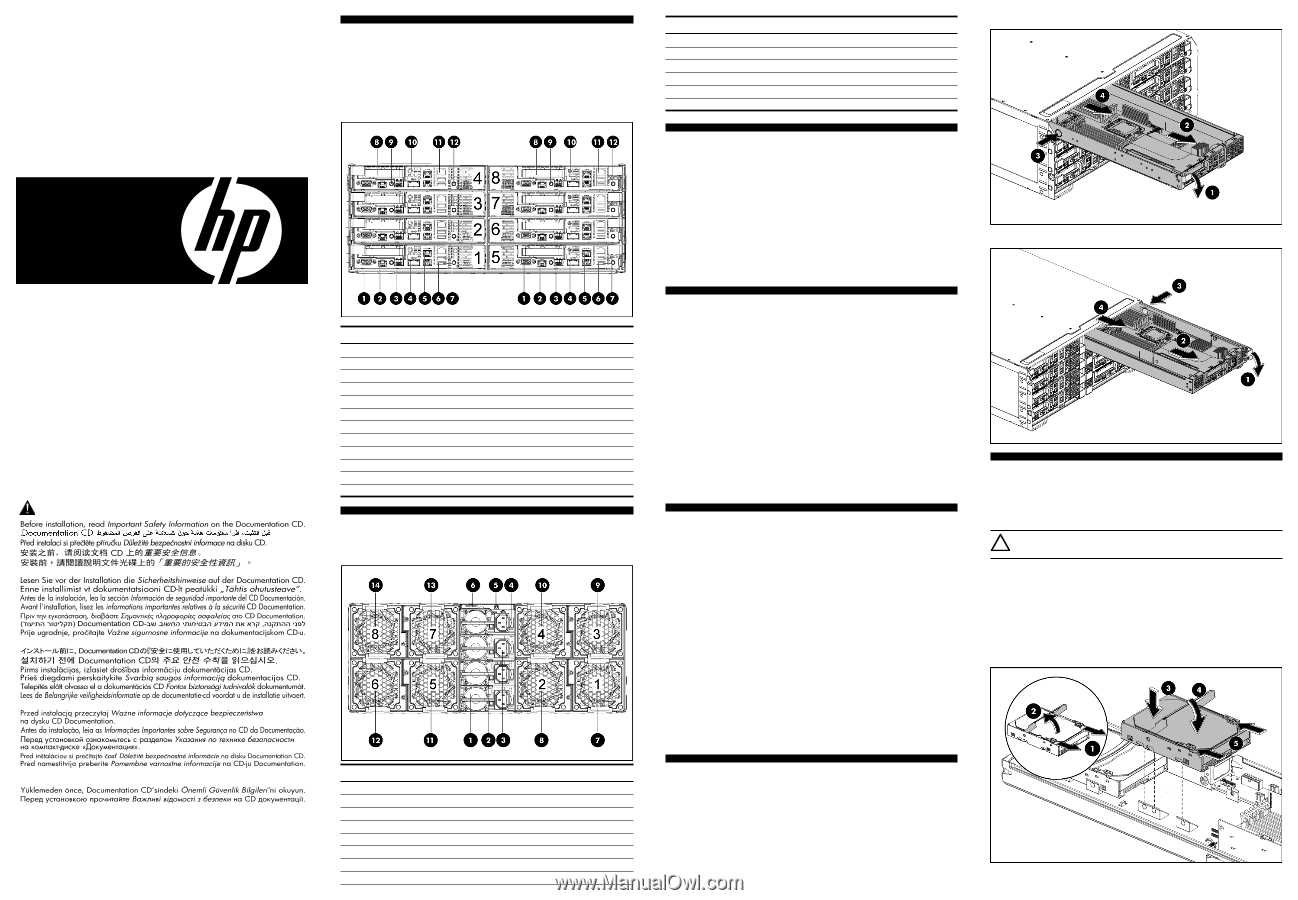
Identifying Server Components
Front Panel Components
SL390s 1U Server Front Panel Components
Figure 1
Front panel components of the s6500 chassis with 8 SL390s 1U servers
Item
Description
1
VGA port
2
Serial port
3
SFP PLUS connector
4
QSFP
5
NIC1/ iLO3 connector
6
NIC2
connector
7
USB connectors
8
Front PCIe bracket (LP slot)
9
Power LED/SW
10
Health LED
11
iLO3 network port
12
UID LED/SW
Rear Panel Components
Figure 2
Rear panel components of the s6500 chassis with 8 SL390s 1U servers
Item
Description
1
Power Supply 1
2
Power Supply 2
3
Power Supply 3
4
Power Supply 4
5
UID LED
6
APM connector
7
Fan 1
8
Fan 2
Item
Description
9
Fan 3
10
Fan 4
11
Fan 5
12
Fan 6
13
Fan 7
14
Fan 8
Server Configuration Resources
In addition to this Installation Sheet, other resources are available for more
information regarding the configuration and maintenance of your server:
•
For safety information and detailed procedures relating to installation of options,
refer to any installation instructions that came with the option, as well as the
HP
ProLiant SL390s G7 1U half width Server Maintenance and Service Guide
.
•
For safety information, regulatory notices, and detailed procedures related to
the rest of the steps listed in the “Configuring the Server” section, refer to the
relevant chapter of the
HP ProLiant SL390s G7 1U half width Server
User Guide
.
•
You can also access additional information and documentation from the
HP website at
.
Server Configuration Overview
The steps listed below give an overview of the necessary setup procedures for
preparing the HP ProLiant SL390s Server for operation:
1.
Connect the AC power cord and peripheral devices.
2.
Power up the server.
3.
Press “F9” to enter BIOS setup.
4.
Note the server BIOS version.
5.
Verify the server BIOS version against the latest BIOS version listed for this
server on the HP website:
.
6.
If you do not have the latest BIOS, update the BIOS now. Refer to the
HP
ProLiant SL390s G7 1U half width Server User Guide
available on the HP
website:
.
7.
Install a supported operating system of your choice. For detailed procedures,
refer to the documentation provided by the operating system vendor. For a list
of operating systems supported by your ProLiant server, go to
s.
Pre- and Post-installation
Procedures
When installing additional options in your HP ProLiant SL390s G7 1U half width
Server, observe the following procedures:
Pre-installation procedures
1.
Turn off the server and all the peripherals connected to it.
2.
Remove the server from the chassis by following the procedure described later
in the “Removing the server” section.
Post-installation procedures
1.
Be sure all components are installed according to the described step-by-step
instructions.
2.
Check to make sure you have not left loose tools or parts inside the server.
3.
Reinstall the PCI riser, peripherals, and system cables that you have removed.
4.
Reinstall the server into the chassis.
5.
Connect all external cables to the system.
6.
Press the power button on the front panel to turn on the server.
Removing the Server
You need to remove the server from the chassis before you can remove or replace a
server component.
To remove server:
1.
Release the handle.
2.
Extend the server from the chassis until the release latch catches.
3.
Firmly holding the server, press the release button.
4.
Remove the server from chassis.
5.
Install the server blank in the server slot.
Figure 3
Removing the SL390s 1U left server
Figure 4
Removing the SL390s 1U right server
Installing the Hard Disk Drive
One SL390s 1U server tray can accommodate up to 2 LFF or 4 SFF hard disk
drives, one chassis can accommodate 8 1U server trays for up to 16 LFF or 32
SFF hard disk drives. The server supports both SAS and SATA hard disk drives
and SSDs.
CAUTION:
Drives can be damaged by static electricity. Before handling
drives, touch an unpainted metal surface to discharge static electricity.
To install LFF hard disk drive on one side of server tray:
1.
Unlock the HDD carrier latches.
2.
Rotate the HDD carrier handle up.
3.
Insert the HDD carrier and align the pins.
4.
Rotate the HDD carrier handle down.
5.
Lock the HDD carrier latches.
Figure 5
Installing the hard disk drive
Important Safety Information
Les "Viktig sikkerhetsinformasjon" på dokumentasjons-CDen før du installerer dette produktet.
Læs dokumentet Vigtige sikkerhedsoplysninger på dokumentations-cd'en, før produktet installeres.
Prima dell'installazione, leggere sul CD le Informazioni importanti sulla sicurezza.
Tärkeisiin turvatietoihin" Documentation CD -levyllä ennen tuotteen asentamista.
Läs dokumentet Viktig säkerhetsinformation på dokumentations-cd:n innan du installerar denna produkt.
Legal notices
© Copyright 2010 Hewlett-Packard Development Company, L.P.
The information contained herein is subject to change without notice. The only warranties for HP
products and services are set forth in the express warranty statements accompanying such products
and services. Nothing herein should be construed as constituting an additional warranty. HP shall
not be liable for technical or editorial errors or omissions contained herein.
Microsoft, Windows, and Windows NT are U.S. registered trademarks of Microsoft Corporation.