HP ProLiant SL390s HP ProLiant SL390s G7 1U half width Server Installation She - Page 2
Installing the Memory Module, Installing the Processor, Installing the raid controllers with, - proliant sl390
 |
View all HP ProLiant SL390s manuals
Add to My Manuals
Save this manual to your list of manuals |
Page 2 highlights
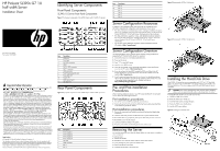
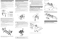
Installing the Memory Module The following guidelines must be followed when memory modules are being added or replaced: • Support 12 DDR3 240-pin RDIMM (SR, DR, QR) or UDIMM (SR, DR) slots(6 DIMMs per CPU) • Channel 0 is located furthest to processor, followed by channel 1 then channel 2 • DIMM 0 is the furthest from the processor of the two DIMMs in a given channel • DIMM Capacity up to 16G • Speed is 800 MHz, 1067 MHz, 1333 MHz depending on DIMM population • DIMM Voltage is 1.5V and LV 1.35V • Support all valid DIMM configurations as long as the total node power is rated below the maximum value Figure 6 Population Order of DIMM Sockets Installing the Processor The HP ProLiant SL390s server supports Intel Nehalem and Westmere Processors High Wattage 130W,95W,80W (Dual CPUs 64-bit), and Nehalem Processors Low Wattage 60W and Westmere Processor Low Wattage 40W(Dual CPUs 64-bit). NOTE: If one processor is being installed, it should be installed in the socket furthest from the IOH/chipset. To install the processor: CAUTION: Use the process install tool to insert the processor into the socket. The processor and system board spare part kits contain the processor install tool and instructions on how to use the tool. It is important to follow the instructions to prevent damage to the pins in the processor socket. 1. Insert the processor in the tool. 2. Align the processor installation tool with the socket and install the processor. 3. Press down firmly until the processor installation tool clicks and separates from the processor, and then remove the processor installation tool. 4. Close the processor socket retaining bracket and the processor retaining latch Figure 8 Installing the processor IMPORTANT: If the heat sink has been removed for any reason, it is critical that you apply more thermal interface material to the integrated heat spreader on the processor to ensure proper thermal bonding between the processor and the heat sink. Clean the contact surface of both the processor and heat sink with an alcohol pad, then re-apply an HP-approved thermal interface material before reinstalling the processor. Use a pattern of five dots when applying the thermal interface material- one dot in the center, and one dot at each corner. NOTE: Do not over tighten the heat sink's spring-loaded screws to prevent them from breaking off. Installing the raid controllers with Battery-backed write cache IMPORTANT: Remove the plastic bracket from the metal bracket before installing the plastic bracket into the chassis. 1. Unfasten the screws and lifting the plastic BBWC bracket out. Figure 10 Removing the plastic BBWC bracket from the metal bracket Figure 12 Installing the BBWC 4. Connecting the BBWC cable with the smart array controllers. Figure 13 Cable routing NOTE: The DIMM should be installed from the furthest A channel DIMM slot. NOTE: It is recommended to install memory in pairs. CAUTION: DIMMs can be damaged by improper handling. Always use an anti-static wrist strap and grounding mat, and discharge static electricity before touching DIMMs. To install a memory module: 1. Align the notch on the bottom edge of the module with the keyed surface of the DIMM slot and then press the module fully into the slot. 2. Firmly press the holding clips inward to secure the memory module in place. Figure 7 Installing the memory module For processor removal, reverse the above installation procedures. CAUTION: To prevent the heat sink from tilting to one side during installation/removal, turn each screw a couple of turns, alternatively between both of them, and then apply the final torque. Do not over tighten the spring loaded screws to prevent them from breaking off. A maximum torque of 4.5 inch-lb is set for each screw. To install the heat sink: 1. Properly align the heat sink mounting pins to the system board mounting holes. 2. Tighten the mounting pins clockwise to secure the heat sink connection to the system board. Figure 9 Installing the heat sink assembly 2. Align the BBWC bracket to the tray and fasten the screws. Figure 11 Installing the BBWC bracket Additional Documentation You can access additional information and documentation from the HP external website. DIMM slots are structured to ensure proper installation. If you insert a DIMM but it does not fit easily into the slot, you may have inserted it incorrectly. Reverse the orientation of the DIMM and insert it again. 3. Install the BBWC into the tray and slide it in the direction of the arrow. CAUTION: Be sure that the heat sink sits squarely on the processor, or overheating and damage to the processor may occur.
-
 1
1 -
 2
2
 |
 |
