HP StorageWorks 4/8 HP StorageWorks DC and DC04 SAN Backbone Director Switches - Page 38
Removing the chassis door, Installing the chassis in the cabinet
 |
View all HP StorageWorks 4/8 manuals
Add to My Manuals
Save this manual to your list of manuals |
Page 38 highlights
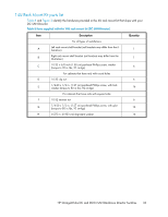
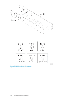
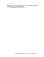
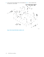
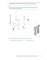
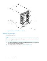
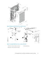
5. Attach the clip or retainer nuts to the vertical rails on the exhaust aisle side of the cabinet (see Figure 5). These clip nuts are used for securing the port side of the chassis to the rack rails using 10-32 x 5/8-inch screws. Use three clips on each rail. Place the clips in optimum locations for securing the chassis to the rails. NOTE: Do not align the clip or retainer nuts with the top or bottom holes of the mounting bracket because the door will interfere with the screw heads. • For rails with round holes: Attach clip nuts (Item D) to each of the front rails. • For rails with square holes: Attach retainer nuts (Item F) to each of the front rails. CAUTION: Use the screws specified in the procedure. Using longer screws can damage the chassis. Removing the chassis door See "Removing the chassis door" on page 73 to remove the chassis door. Installing the chassis in the cabinet To install the DC SAN Director in the cabinet: CAUTION: A fully populated DC SAN Director (eight FC8-48 port cards, 384 ports) weighs approximately 104 kg (228 lbs) and requires a hydraulic or assisted lift to install it. 1. Use a lift to raise the chassis to the correct level. 2. Move the lift as close as possible to the rack, with the air-intake side of the chassis facing the front of the rack (see Figure 6). 3. If applicable, lock the wheels of the lift. 4. Gently slide the chassis onto the shelf brackets, ensuring that it remains supported during the transfer. 38 DC SAN Director Installation
-
 1
1 -
2
-
3
-
4
-
5
-
6
-
7
-
8
-
9
-
10
-
11
-
12
-
13
-
14
-
15
-
16
-
17
-
18
-
19
-
20
-
21
-
22
-
23
-
24
-
25
-
26
-
27
-
28
-
29
-
30
-
31
-
32
-
 33
33 -
 34
34 -
 35
35 -
 36
36 -
 37
37 -
 38
38 -
 39
39 -
 40
40 -
 41
41 -
 42
42 -
 43
43 -
44
-
45
-
46
-
47
-
48
-
49
-
50
-
51
-
52
-
53
-
54
-
55
-
56
-
57
-
58
-
59
-
60
-
61
-
62
-
63
-
64
-
65
-
66
-
67
-
68
-
69
-
70
-
71
-
72
-
73
-
74
-
75
-
76
-
77
-
78
-
79
-
80
-
81
-
82
-
83
-
84
-
85
-
86
-
87
-
88
-
89
-
90
-
91
-
92
-
93
-
94
-
95
-
96
-
97
-
98
-
99
-
100
-
101
-
102
-
103
-
104
-
105
-
106
-
107
-
108
-
109
-
110
-
111
-
112
-
113
-
114
-
115
-
116
-
117
-
118
-
119
-
120
-
121
-
122
-
123
-
124
-
125
-
126
-
127
-
128
-
129
-
130
-
131
-
132
-
133
-
134
-
135
-
136
-
137
-
138
-
139
-
140
-
141
-
142
-
143
-
144
-
145
-
146
-
147
-
148
-
149
-
150
-
151
-
152
-
153
-
154
-
155
-
156
-
157
-
158
-
159
-
160
-
161
-
162
-
163
-
164
-
165
-
166
-
167
-
168
-
169
-
170
-
171
-
172
-
173
-
174
-
175
-
176
-
177
-
178
-
179
-
180
-
181
-
182
-
183
-
184
-
185
-
186
-
187
-
188
-
189
-
190
-
191
-
192
-
193
-
194
-
195
-
196
-
197
-
198
-
199
-
200
-
201
-
202
-
203
-
204
-
205
-
206
-
207
-
208
-
209
-
210
-
211
-
212
-
213
-
214
-
215
-
216
-
217
-
218
-
219
-
220
-
221
-
222
-
223
-
224
-
225
-
226
-
227
-
228
-
229
-
230
-
231
-
232
-
233
-
234
-
235
-
236
-
237
-
238
-
239
-
240
-
241
-
242
-
243
-
244
-
245
-
246
-
247
-
248
-
249
-
250
-
251
-
252
-
253
-
254
-
255
-
256
 |
 |
