HP TC1000 Maintenance and Service Guide, Compaq Tablet PC TC1000
HP TC1000 - Compaq Tablet PC Manual
 |
UPC - 613326724071
View all HP TC1000 manuals
Add to My Manuals
Save this manual to your list of manuals |
HP TC1000 manual content summary:
- HP TC1000 | Maintenance and Service Guide, Compaq Tablet PC TC1000 - Page 1
PC TC1000 Document Part Number: 268627-001 April 2003 This guide is a troubleshooting reference used for maintaining and servicing the tablet PC. It provides comprehensive information on identifying tablet PC features, components, and spare parts, troubleshooting tablet PC problems, and performing - HP TC1000 | Maintenance and Service Guide, Compaq Tablet PC TC1000 - Page 2
without notice. The warranties for HP products are set forth in the express limited warranty statements accompanying such products. Nothing herein should be construed as constituting an additional warranty. Maintenance and Service Guide First Edition April 2003 Document Part Number: 268627-001 - HP TC1000 | Maintenance and Service Guide, Compaq Tablet PC TC1000 - Page 3
1-10 1.4 Power Management 1-11 1.5 Tablet PC External Components 1-12 1.6 Keyboard Components 1-24 1.7 Docking Station Components 1-30 1.8 Design Overview 1-34 2 Troubleshooting 2.1 Computer Setup and Diagnostics Utilities 2-1 Selecting Computer Setup or Compaq Diagnostics 2-1 Selecting - HP TC1000 | Maintenance and Service Guide, Compaq Tablet PC TC1000 - Page 4
5-4 5.4 Real Time Clock (RTC) Battery 5-11 5.5 Display Panel Assembly 5-12 5.6 Speaker Assembly 5-21 5.7 Digitizer Cable 5-23 5.8 System Board 5-24 5.9 Fan and Heat Sink 5-31 5.10 Modem Cable 5-34 5.11 Switch Board 5-35 5.12 Docking Station 5-37 iv Maintenance and Service Guide - HP TC1000 | Maintenance and Service Guide, Compaq Tablet PC TC1000 - Page 5
Contents 6 Specifications A Connector Pin Assignments B Power Cord Set Requirements 3-Conductor Power Cord Set B-1 General Requirements B-1 Country-Specific Requirements B-2 Notes B-3 C Screw Listing Index Maintenance and Service Guide v - HP TC1000 | Maintenance and Service Guide, Compaq Tablet PC TC1000 - Page 6
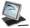
on the tablet PC is the tablet PC pen. Handwriting recognition software is available in Microsoft Windows XP Tablet PC Edition, the operating system installed on the tablet PC. Figure 1-1. Compaq Tablet PC TC1000 The optional keyboard is 95 percent the size of a full-size notebook keyboard and - HP TC1000 | Maintenance and Service Guide, Compaq Tablet PC TC1000 - Page 7
Product Description The optional docking station provides access to a MultiBay and a variety of connectors. Figure 1-2. Compaq Tablet PC TC1000 with Optional Keyboard and Optional Docking Station 1-2 Maintenance and Service Guide - HP TC1000 | Maintenance and Service Guide, Compaq Tablet PC TC1000 - Page 8
designator C=Compaq TC1000=Tablet PC 2 CD-RW combination drive 0=no optical drive 7 Integrated communication 8=combination modem/NIC/wireless LAN C=combination modem/NIC 8 RAM 25=256 MB 9 Operating system T=Microsoft Windows XP Tablet Edition 10 SKU Maintenance and Service Guide - HP TC1000 | Maintenance and Service Guide, Compaq Tablet PC TC1000 - Page 9
Description Table 1-2 Compaq Tablet PC TC1000 Models The following Compaq Tablet PC TC1000 models use config. code LBSZ and feature: ■ Pen and PointStick keyboard ■ 6-cell, 4.0 Ah lithium ion (Li ion) battery pack ■ 16 MB of discrete video memory ■ 3-year warranty on parts and labor CTC1000 - HP TC1000 | Maintenance and Service Guide, Compaq Tablet PC TC1000 - Page 10
Switzerland United Kingdom 470045-209 470045-210 470045-211 470045-212 470045-213 The following Compaq Tablet PC TC1000 models use config. code LBQZ and feature: ■ Pen and PointStick keyboard ■ 6-cell, 4.0 Ah Li ion battery pack ■ 16 MB of discrete video memory ■ 1-year warranty on parts and labor - HP TC1000 | Maintenance and Service Guide, Compaq Tablet PC TC1000 - Page 11
Compaq Tablet PC TC1000 models and use config. code LBQZ. These tablet PC models feature: ■ Pen and PointStick keyboard ■ 6-cell, 4.0 Ah Li ion battery pack ■ 16 MB of discrete video memory ■ 1-year warranty on parts T 100 X0 60 0 C 25 T United States 470046-349 1-6 Maintenance and Service Guide - HP TC1000 | Maintenance and Service Guide, Compaq Tablet PC TC1000 - Page 12
Product Description Table 1-2 Compaq Tablet PC TC1000 Models (Continued) CTC1000 T 100 X0 30 0 8 76 T United States 470046-342 CTC1000 T 100 X0 30 0 8 38 T United 30 0 C 38 T United States 470046-347 CTC1000 T 100 X0 30 0 C 25 T United States 470046-346 Maintenance and Service Guide 1-7 - HP TC1000 | Maintenance and Service Guide, Compaq Tablet PC TC1000 - Page 13
pack ■ 60-, 40-, or 30-GB high-capacity SMART hard drive, varying by tablet PC model ■ Support for the following drives through the MultiBay (with optional external MultiBay or docking station): ❏ 1.44-MB diskette drive ❏ 24X Max CD-ROM drive ❏ 8X Max CD-RW drive 1-8 Maintenance and Service Guide - HP TC1000 | Maintenance and Service Guide, Compaq Tablet PC TC1000 - Page 14
connectors on the tablet PC: ❏ PC Card slot ❏ CompactFlash card slot ❏ RJ-45 network ❏ RJ-11 modem ❏ Universal Serial Bus ❏ External monitor ❏ AC power ❏ Stereo line out/headphone ❏ Mono microphone ❏ external MultiBay ❏ optional keyboard ❏ optional docking station ■ Support for the following - HP TC1000 | Maintenance and Service Guide, Compaq Tablet PC TC1000 - Page 15
(refer to Section 5.4, "Real Time Clock (RTC) Battery"). 3. Wait approximately five minutes. 4. Replace the RTC battery and reassemble the tablet PC. Do not reinsert the battery pack at this time. 5. Connect AC power to the tablet PC. 6. Turn on the tablet PC. All passwords and all CMOS settings - HP TC1000 | Maintenance and Service Guide, Compaq Tablet PC TC1000 - Page 16
tablet PC supports the following power management features: ■ Suspend ■ Hibernation ■ Setting customization by the user ■ Hotkeys for setting level of performance ■ Smart battery that provides an accurate battery power gauge ■ Battery calibration ■ Lid switch Suspend/resume ■ Power/Suspend button - HP TC1000 | Maintenance and Service Guide, Compaq Tablet PC TC1000 - Page 17
Description 1.5 Tablet PC External Components The external components on the front panel of the tablet are shown in Figure 1-3 and described in Table 1-3. Figure 1-3. Front Panel Components Table 1-3 Front Panel Components Item 1 Component Wireless LAN activity light 2 Battery light Function - HP TC1000 | Maintenance and Service Guide, Compaq Tablet PC TC1000 - Page 18
Journal launch button 5 Tablet PC Input Panel launch button 6 Rotate button 7 Microphone Function On: AC power is being supplied through the AC adapter. When the tablet PC is in Windows, opens and closes the Microsoft Journal application, which supports handwriting. When the tablet PC is in - HP TC1000 | Maintenance and Service Guide, Compaq Tablet PC TC1000 - Page 19
device. Ejects an optional PC Card from the PC Card slot. Supports an optional Type I or Type II 32-bit (CardBus) or 16-bit PC Card. Secures the pen to the tablet PC. Used with the tether eyelet on the pen, enables you to tether the pen to the tablet PC. 1-14 Maintenance and Service Guide - HP TC1000 | Maintenance and Service Guide, Compaq Tablet PC TC1000 - Page 20
power connector Function Ejects an optional CompactFlash card from the CompactFlash card slot. Supports an optional Type I or Type II CompactFlash card. Connects an optional USB 2.0- or 1.1-compliant device. Connects a modem cable. Connects an Ethernet network cable. Both lights off: The tablet PC - HP TC1000 | Maintenance and Service Guide, Compaq Tablet PC TC1000 - Page 21
Left Side Components Table 1-5 Left Side Components Item Component 1 Security cable slot 2 Screen protector slots (2) Function Attaches an optional security cable to the tablet PC. Secure the optional screen protector when it is attached to the tablet PC. 1-16 Maintenance and Service Guide - HP TC1000 | Maintenance and Service Guide, Compaq Tablet PC TC1000 - Page 22
Accepts an alignment key to safeguard attachment procedures. For example, matching the alignment key on an optional tablet PC keyboard to the alignment key slot helps you correctly orient the tablet PC to the keyboard as you attach the tablet PC to the keyboard. Maintenance and Service Guide 1-17 - HP TC1000 | Maintenance and Service Guide, Compaq Tablet PC TC1000 - Page 23
to enter a command. ■ Rotate upward to scroll upward. ■ Rotate downward to scroll downward. While the tablet PC is: ■ Starting up and a flashing pointer is displayed on the screen, opens the Setup utility. ■ In Windows, functions like esc on a standard keyboard. 1-18 Maintenance and Service Guide - HP TC1000 | Maintenance and Service Guide, Compaq Tablet PC TC1000 - Page 24
tablet PC from Hibernation. If the system has stopped responding and Windows shutdown procedures cannot be used, slide and hold for 4 seconds to turn off the tablet PC. On: Tablet PC is on. Flashing: Tablet PC is in Standby. Off: Tablet PC is off or in Hibernation. Maintenance and Service Guide - HP TC1000 | Maintenance and Service Guide, Compaq Tablet PC TC1000 - Page 25
Tablet PC Docking Station. Produce stereo sound. Connects optional stereo headphones or powered stereo speakers. Connects an optional headset, such as a mobile telephone headset with a microphone and a monaural ear piece. Connects an optional monaural microphone. 1-20 Maintenance and Service Guide - HP TC1000 | Maintenance and Service Guide, Compaq Tablet PC TC1000 - Page 26
used in portrait orientation as a free-standing tablet, can elevate the top of the tablet PC to provide a comfortable writing and viewing angle. Accepts the docking restraint latch on an optional docking station to secure the tablet PC to the docking station. Maintenance and Service Guide 1-21 - HP TC1000 | Maintenance and Service Guide, Compaq Tablet PC TC1000 - Page 27
Contains the serial number of the tablet PC and a code describing the original configuration of the tablet PC. You will need the serial number if you call Compaq customer support. 4 Docking connector Connects the tablet PC to an optional docking station. 5 Air vent Allows airflow to cool - HP TC1000 | Maintenance and Service Guide, Compaq Tablet PC TC1000 - Page 28
battery pack from the battery bay. Secure the memory and Mini PCI compartment cover to the tablet PC. Contains one memory slot for a PC133-compliant memory module. Also holds an optional Mini PCI board, such as a modem board or a combination modem and wireless board. Maintenance and Service Guide - HP TC1000 | Maintenance and Service Guide, Compaq Tablet PC TC1000 - Page 29
1-9. Keyboard Front Panel Components Table 1-9 Keyboard Front Panel Components Item Component 1 Alignment key 2 Keyboard hooks (2) Function Ensures the tablet PC is attached to the keyboard in the correct orientation. Secure the tablet PC to the keyboard. 1-24 Maintenance and Service Guide - HP TC1000 | Maintenance and Service Guide, Compaq Tablet PC TC1000 - Page 30
while it is connected to the keyboard. Help guide the tablet PC and keyboard into an optional Tablet PC Docking Station. Enables the optional docking station to be connected to the tablet PC while the keyboard is attached to the tablet PC. Moves the cursor and selects and activates items - HP TC1000 | Maintenance and Service Guide, Compaq Tablet PC TC1000 - Page 31
Product Description The external components on the front panel of the keyboard are shown in Figure 1-10 and described in Table 1-10. Figure 1-10. Keyboard Front Panel Components 1-26 Maintenance and Service Guide - HP TC1000 | Maintenance and Service Guide, Compaq Tablet PC TC1000 - Page 32
, press Fn+F11/F12. Combines with other keys to perform system tasks. For example, pressing Fn+num lk turns on the keypad. Used like an external numeric keypad. Displays the Microsoft Windows Start Menu. Displays a shortcut menu for items beneath the pointer. Maintenance and Service Guide 1-27 - HP TC1000 | Maintenance and Service Guide, Compaq Tablet PC TC1000 - Page 33
Product Description The components on the rear panel and bottom of the optional keyboard are shown in Figure 1-11 and described in Table 1-11. Figure 1-11. Keyboard Rear Panel and Bottom Components 1-28 Maintenance and Service Guide - HP TC1000 | Maintenance and Service Guide, Compaq Tablet PC TC1000 - Page 34
screen protector, from the keyboard. Secure the portfolio or optional screen protector to the keyboard. Accepts an alignment key to ensure proper orientation. Maintenance and Service Guide 1-29 - HP TC1000 | Maintenance and Service Guide, Compaq Tablet PC TC1000 - Page 35
Product Description 1.7 Docking Station Components The front and left side components on the optional docking station are shown in Figure 1-12 and described in Table 1-12. Figure 1-12. Docking Station Front and Left Side Components 1-30 Maintenance and Service Guide - HP TC1000 | Maintenance and Service Guide, Compaq Tablet PC TC1000 - Page 36
PC. Secures the tablet PC to the docking stand. Fit into the tablet PC docking alignment slots to align the tablet PC in the docking stand. Attaches an optional security cable to the tablet PC. Ejects a MultiBay device from the bay. Connects optional USB devices. Maintenance and Service Guide - HP TC1000 | Maintenance and Service Guide, Compaq Tablet PC TC1000 - Page 37
Product Description The rear panel and right side components on the optional docking station are shown in Figure 1-13 and described in Table 1-13. Figure 1-13. Docking Station Rear Panel and Right Side Components 1-32 Maintenance and Service Guide - HP TC1000 | Maintenance and Service Guide, Compaq Tablet PC TC1000 - Page 38
6 Audio line-out jack 7 USB connectors (3) 8 AC power connector Function Tilts the docking stand forward and backward to enable different viewing angles and different docking modes. Supports a diskette drive, CD-ROM or CD-RW drive, DVD drive, CD-RW/DVD drive, or second hard drive. Connects - HP TC1000 | Maintenance and Service Guide, Compaq Tablet PC TC1000 - Page 39
temperatures, system power consumption, power management/battery conservation configurations, battery fast charging, and software applications. Exhaust air is displaced through the ventilation grill located on the left side of the tablet PC. Ä CAUTION: To properly ventilate the tablet PC, allow - HP TC1000 | Maintenance and Service Guide, Compaq Tablet PC TC1000 - Page 40
The tablet PC features two Compaq system management utilities: ■ Computer Setup-A system information and customization utility that can be used even when your operating system is not working or will not load. This utility includes settings that are not available in Windows. Maintenance and Service - HP TC1000 | Maintenance and Service Guide, Compaq Tablet PC TC1000 - Page 41
information. ❏ Test system components. ❏ Troubleshoot a device configuration problem in Windows 2000, Windows XP Professional, or Windows XP Home. ✎ It is not necessary to configure a device connected to a USB connector on the tablet PC or an optional docking base. Using Computer Setup Information - HP TC1000 | Maintenance and Service Guide, Compaq Tablet PC TC1000 - Page 42
identification information about the tablet PC, a docking base, and any battery packs in the system. ■ View specification information about the processor, memory and cache size, and system ROM. Save system configuration settings to a diskette. Restore system configuration settings from a diskette - HP TC1000 | Maintenance and Service Guide, Compaq Tablet PC TC1000 - Page 43
Diskette write* ■ CD-ROM or diskette startup ✎ Settings for a DVD-ROM can be entered in the CD-ROM field. System IDs Enter identification numbers for the tablet PC, a docking base, and all battery packs in the system. *Not applicable to SuperDisk LS-120 drives. 2-4 Maintenance and Service Guide - HP TC1000 | Maintenance and Service Guide, Compaq Tablet PC TC1000 - Page 44
USB legacy support is enabled, the keyboard works even when a Windows operating system is not loaded.) ■ Set an optional external monitor or overhead projector connected to a video card in a docking base as the primary device. (When the tablet PC display is set as secondary, the tablet PC must be - HP TC1000 | Maintenance and Service Guide, Compaq Tablet PC TC1000 - Page 45
(default), PAL, NTSC-J, or PAL-M.* ■ Enable/disable all settings in the SpeedStep window. (When Disable is selected, the tablet PC runs in Battery Optimized mode.) ■ Specify how the tablet PC recognizes multiple identical docking bases that are identically equipped. (Select Disable to recognize the - HP TC1000 | Maintenance and Service Guide, Compaq Tablet PC TC1000 - Page 46
Troubleshooting 2.2 Using Compaq Diagnostics When you access Compaq Diagnostics, a scan of all system components is displayed on the screen before the Compaq Diagnostics window opens. You can display more or less information from anywhere within Compaq Diagnostics by selecting Level on the menu bar. - HP TC1000 | Maintenance and Service Guide, Compaq Tablet PC TC1000 - Page 47
. ❏ Custom Test-Performs maximum testing on a selected device. ◆ To run all tests for your selected device, select the Check All button. ◆ To run only the tests you select, select the Uncheck All button, then select the checkbox for each test you want to run. 2-8 Maintenance and Service Guide - HP TC1000 | Maintenance and Service Guide, Compaq Tablet PC TC1000 - Page 48
the tablet PC with their error codes. 8. Select a tab to save the report: ❏ Log tab-Select the Log tab Save button. ❏ Error tab-Select the Error tab Save button. 9. Select a tab to print the report: ❏ Log tab-Select File > Save As, then print the file from your folder. Maintenance and Service Guide - HP TC1000 | Maintenance and Service Guide, Compaq Tablet PC TC1000 - Page 49
2.15 2.16 2.17 2.18 2.19 2.20 Description Initial troubleshooting No power, part 1 No power, part 2 No power, part 3 No power, part 4 No video, part 1 No video, part 2 Nonfunctioning docking station No operating system (OS) loading No OS loading from hard drive, part 1 No OS loading from hard drive - HP TC1000 | Maintenance and Service Guide, Compaq Tablet PC TC1000 - Page 50
Flowchart 2.1-Initial Troubleshooting Begin troubleshooting. N Is there power? Y Go to Section 2.2, No Power. N Beeps, LEDs, or error messages? Y Check LED board, speaker connections. N Is there video? Device. Go to Section 2.20, No Network or Modem. End Maintenance and Service Guide 2-11 - HP TC1000 | Maintenance and Service Guide, Compaq Tablet PC TC1000 - Page 51
Power up in docking station? *NOTES: 1. On some models there is a separate reset button. 2. On some models the tablet PC may be reset using the Suspend switch and either the lid switch or the main power switch. Go to Section 2.8, Nonfunctioning Docking Station. 2-12 Maintenance and Service Guide - HP TC1000 | Maintenance and Service Guide, Compaq Tablet PC TC1000 - Page 52
Troubleshooting Flowchart 2.3-No Power, Part 2 Continued from Section 2.2, No Power, Part 1. Visually check for debris in battery socket and clean if necessary. Y Power on? N Done Check battery by recharging, moving it to another tablet PC, or replacing it. N Power on? Y Replace power supply ( - HP TC1000 | Maintenance and Service Guide, Compaq Tablet PC TC1000 - Page 53
Troubleshooting Flowchart 2.4-No Power, Part 3 Continued from Section 2.3, No Power, Part 2. Plug directly into AC outlet. Y Power LED on? N Reseat AC adapter in tablet PC and at power source. Y Power on? N N Power outlet active? Y Replace power cord. Y Power on? N Done Done Try different - HP TC1000 | Maintenance and Service Guide, Compaq Tablet PC TC1000 - Page 54
No Power, Part 4 Continued from Section 2.4, No Power, Part 3. Troubleshooting Open tablet PC. Y Loose or damaged parts? N Reseat loose components and boards and replace damaged items. Close tablet PC and retest. N Power on? Y Done Replace the following items (if applicable). Check tablet PC - HP TC1000 | Maintenance and Service Guide, Compaq Tablet PC TC1000 - Page 55
after each replacement. 1. Cable between notebook and tablet PC display (if applicable) 2. Inverter board (if applicable) 3. Display 4. System board N N Video OK? Try another display. Internal and external video OK? Replace system board. Y Y Done Done 2-16 Maintenance and Service Guide - HP TC1000 | Maintenance and Service Guide, Compaq Tablet PC TC1000 - Page 56
Troubleshooting Flowchart 2.7-No Video, Part 2 Continued from Section 2.6, No Video, Part 1. Remove tablet PC from docking station, if connected. Adjust display brightness. Check brightness of external monitor. N Video OK? Y Go to "A" in Section 2.6, No Video, Part 1. Y Video OK? N Check - HP TC1000 | Maintenance and Service Guide, Compaq Tablet PC TC1000 - Page 57
PC, reseat all internal parts, and replace any damaged items in docking station. Done Reinstall tablet PC into docking station. Y Docking station operating? N Done Replace the following docking station components one at a time. Check tablet PC operation after each replacement. 1. Power supply - HP TC1000 | Maintenance and Service Guide, Compaq Tablet PC TC1000 - Page 58
Troubleshooting Flowchart 2.9-No Operating System (OS) Loading No OS Loading.* Reseat power cord in docking station and power outlet. No OS loading from hard drive, go to Section 2.10. No OS loading from diskette drive, go to Section 2.13. No OS loading from CD- or DVD-ROM drive, go to Section 2. - HP TC1000 | Maintenance and Service Guide, Compaq Tablet PC TC1000 - Page 59
Troubleshooting Flowchart 2.10-No OS Loading from Hard Drive, Part 1 OS not loading from hard drive. Y Nonsystem disk message? N Reseat external hard drive. Go to Section 2.11, No OS Loading from Hard Drive, Part 2. Y OS loading? N N Boot from CD Device. 2-20 Maintenance and Service Guide - HP TC1000 | Maintenance and Service Guide, Compaq Tablet PC TC1000 - Page 60
, then format hard drive to bootable C:\ prompt. Hard drive formatted? Y Format hard drive and bring to a bootable Y C:\ prompt. Tablet PC booted? N Go to Section 2.12, No OS Loading from Hard Drive, Part 3. Load OS using Restore CD (if applicable). Maintenance and Service Guide 2-21 - HP TC1000 | Maintenance and Service Guide, Compaq Tablet PC TC1000 - Page 61
Troubleshooting Flowchart 2.12-No OS Loading from Hard Drive, Part 3 Continued from Section 2.11, No OS Loading from Hard Drive, Part 2. N System files on hard drive? Y Install OS and reboot. Y Virus on hard drive hard drive. Y Done Replace hard drive. Done 2-22 Maintenance and Service Guide - HP TC1000 | Maintenance and Service Guide, Compaq Tablet PC TC1000 - Page 62
tablet PC. Y Check diskette for system files. Try different diskette. Y Nonsystem disk error? N 1. Replace diskette drive. 2. Replace system board. Y OS loading? N Done Change boot priority using the setup utility. Go to Section 2.17, Nonfunctioning Device. Maintenance and Service Guide - HP TC1000 | Maintenance and Service Guide, Compaq Tablet PC TC1000 - Page 63
Troubleshooting Flowchart 2.14-No OS Loading from CD- or DVD-ROM Drive No OS Loading from Disc CD- or in drive? DVD-ROM Drive. N Y N Bootable disc in drive? Y Install bootable disc and reboot tablet PC. Install bootable disc. Try another bootable disc. Y Boots from CD or DVD? N Done - HP TC1000 | Maintenance and Service Guide, Compaq Tablet PC TC1000 - Page 64
Troubleshooting Flowchart 2.15-No Audio, Part 1 Y No Audio. Turn up audio internally or externally. Audio? Done N Y Tablet PC in docking station (if applicable)? N Undock N Internal audio? Go to Section 2.16, No Audio, Part 2. Y Go to Section 2.16, No Audio, Part 2. Replace the - HP TC1000 | Maintenance and Service Guide, Compaq Tablet PC TC1000 - Page 65
and set configuration in OS. Connect to external speaker. N Audio? Y Replace audio board and speaker connections in tablet PC (if applicable). Y Audio? N Done 1. Replace internal speakers. 2. Replace audio board (if applicable). 3. Replace system board. 2-26 Maintenance and Service Guide - HP TC1000 | Maintenance and Service Guide, Compaq Tablet PC TC1000 - Page 66
2.17-Nonfunctioning Device Nonfunctioning Device. Troubleshooting Reseat device. Unplug the nonfunctioning device from the tablet PC, and inspect cables and plugs for bent or broken pins or other damage. Clear CMOS. Reattach device. Close tablet PC, plug in power, and reboot. N Device boots - HP TC1000 | Maintenance and Service Guide, Compaq Tablet PC TC1000 - Page 67
operating properly. Connect tablet PC to good external keyboard. N External device works? Y Replace system board. Reseat internal keyboard connector (if applicable). N OK? Y Replace internal keyboard or cable. Y Done OK? N Replace system board. Done 2-28 Maintenance and Service Guide - HP TC1000 | Maintenance and Service Guide, Compaq Tablet PC TC1000 - Page 68
. Connect tablet PC to good external pointing device. N External device works? Y Replace system board. Reseat internal pointing device connector (if applicable). N Replace internal OK? pointing device or cable. Y Y Done OK? N Replace system board. Done Maintenance and Service Guide - HP TC1000 | Maintenance and Service Guide, Compaq Tablet PC TC1000 - Page 69
line? N N NIC/modem configured in OS? Y Replace jack or have jack activated. Connect to nondigital line. Reload drivers and reconfigure. Disconnect all power from the tablet PC and open. Reseat NIC/modem (if applicable). Y OK? N Replace NIC/modem (if applicable). Y OK? N Done Done Replace - HP TC1000 | Maintenance and Service Guide, Compaq Tablet PC TC1000 - Page 70
for spare part numbers and option part numbers. 3.1 Serial Number Location When ordering parts or requesting information, provide the tablet PC serial number and model number located on the bottom of the tablet PC (Figure 3-1). Figure 3-1. Serial Number Location Maintenance and Service Guide 3-1 - HP TC1000 | Maintenance and Service Guide, Compaq Tablet PC TC1000 - Page 71
Illustrated Parts Catalog 3.2 Tablet PC System Major Components Figure 3-2. Tablet PC Major Components 3-2 Maintenance and Service Guide - HP TC1000 | Maintenance and Service Guide, Compaq Tablet PC TC1000 - Page 72
Keyboard release assembly Pen holder Pen holder push block assembly Mini PCI communications/memory expansion compartment cover Hard drive cover not illustrated: tablet PC feet Spare Part Number 311062-001 310667-001 310676-001 310666-001 310673-001 310678-001 Maintenance and Service Guide 3-3 - HP TC1000 | Maintenance and Service Guide, Compaq Tablet PC TC1000 - Page 73
Illustrated Parts Catalog Figure 3-2. Tablet PC Major Components 3-4 Maintenance and Service Guide - HP TC1000 | Maintenance and Service Guide, Compaq Tablet PC TC1000 - Page 74
, Type III) Memory expansion board (DDR, 256 MB) Battery pack, Li ion Real time clock (RTC) battery Hard drives 40 GB 30 GB Spare Part Number 310664-001 310665-001 310672-001 310679-001 310671-001 310670-001 310677-001 302119-001 310675-001 311240-001 310668-001 Maintenance and Service Guide 3-5 - HP TC1000 | Maintenance and Service Guide, Compaq Tablet PC TC1000 - Page 75
Catalog 3.3 Miscellaneous Cable Kit Components Figure 3-3. Miscellaneous Cable Kit Components Table 3-2 Miscellaneous Cable Kit Components Spare Part Number 310673-001 Item 1 2 3 4 5 6 Description Modem cable Display panel cable Speaker cable Digitizer cable Display inverter cable Switch board - HP TC1000 | Maintenance and Service Guide, Compaq Tablet PC TC1000 - Page 76
-001 Item 1 2 3 4 5 6 7 8 Description CompactFlash card slot space saver PC Card slot space saver Pen holder push block assembly Pen holder Tablet PC feet (2) Hard drive cover Keyboard release assembly Memory expansion/mini PCI communications compartment cover Maintenance and Service Guide 3-7 - HP TC1000 | Maintenance and Service Guide, Compaq Tablet PC TC1000 - Page 77
Parts Catalog 3.5 Keyboard Figure 3-5. Tablet PC TC1000 Keyboard Table 3-4 Tablet PC TC1000 Keyboard Description Tablet PC TC1000 of China Sweden/Finland Switzerland Taiwan United Kingdom United States Spare Part Number 310681-AD1 310681-091 310681-AA1 310681-101 310681-111 310681-AB1 - HP TC1000 | Maintenance and Service Guide, Compaq Tablet PC TC1000 - Page 78
3.6 Docking Station Illustrated Parts Catalog Figure 3-6. Compaq Tablet PC TC1000 Docking Station Table 3-5 Optional Docking Station Description Tablet PC TC1000 Docking Station Spare Part Number 311063-001 Maintenance and Service Guide 3-9 - HP TC1000 | Maintenance and Service Guide, Compaq Tablet PC TC1000 - Page 79
Illustrated Parts Catalog 3.7 Docking Station Components Figure 3-7. Compaq Tablet PC TC1000 Docking Station Components 3-10 Maintenance and Service Guide - HP TC1000 | Maintenance and Service Guide, Compaq Tablet PC TC1000 - Page 80
Illustrated Parts Catalog Table 3-6 Docking Station Components Item 1 2 3 4 Description Docking stand and pivot arm Top case Board assembly Bottom case Spare Part Number 311189-001 311190-001 311192-001 311191-001 Maintenance and Service Guide 3-11 - HP TC1000 | Maintenance and Service Guide, Compaq Tablet PC TC1000 - Page 81
Pen (uses a 1.5 VDC, AAAA battery) Tablet PC Miscellaneous Screw Kit (includes the following screws; refer to Appendix C, "Screw Listing," for more information on screw specifications and usage.) ■ Phillips M2.0 × 4.0 ■ Phillips M2.0 × 5.0 ■ Phillips M2.0 × 3.5 ■ Torx M2.5 × 7.0 Docking Station - HP TC1000 | Maintenance and Service Guide, Compaq Tablet PC TC1000 - Page 82
This chapter provides essential information for proper and safe removal and replacement service. 4.1 Tools Required You will need the following tools to complete the screwdriver ■ Tool kit (includes connector removal tool, loopback plugs, and case utility tool) Maintenance and Service Guide 4-1 - HP TC1000 | Maintenance and Service Guide, Compaq Tablet PC TC1000 - Page 83
. In all cases, avoid bending, twisting, or tearing cables. Ensure that cables are routed in such a way that they cannot be caught or snagged by parts being removed or replaced. Handle flex cables with extreme care; these cables tear easily. Ä CAUTION: When servicing the tablet PC, ensure that - HP TC1000 | Maintenance and Service Guide, Compaq Tablet PC TC1000 - Page 84
that must be handled with care. To prevent damage to the tablet PC, damage to a removable drive, or loss of information, Avoid dropping drives from any height onto any surface. ■ After removing a hard drive, CD-ROM drive, or a diskette drive, place it in a static-proof bag. ■ and Service Guide 4-3 - HP TC1000 | Maintenance and Service Guide, Compaq Tablet PC TC1000 - Page 85
electrostatic-sensitive parts in their containers until the parts arrive at static-free workstations. ■ Place items on a grounded surface before removing items from their containers. ■ Always be properly grounded when touching a sensitive component or assembly. 4-4 Maintenance and Service Guide - HP TC1000 | Maintenance and Service Guide, Compaq Tablet PC TC1000 - Page 86
reusable electrostatic-sensitive parts from assemblies in properly grounded tools and equipment. ■ Use conductive field service tools, such as cutters, screwdrivers, and vacuums. . ■ Handle electrostatic-sensitive components, parts, and assemblies by the case or PCM laminate. Handle these items - HP TC1000 | Maintenance and Service Guide, Compaq Tablet PC TC1000 - Page 87
system. Wrist straps are flexible straps with a minimum of one megohm ±10% resistance in the ground cords. To provide proper ground, wear a strap snugly against the skin at all times cords of one-megohm resistance ■ Static-dissipative tables or floor mats with hard ties to the ground ■ Field service - HP TC1000 | Maintenance and Service Guide, Compaq Tablet PC TC1000 - Page 88
4-2 Static-Shielding Materials Material Antistatic plastic Carbon-loaded plastic Metallized laminate Use Bags Floor mats Floor mats Voltage Protection Level 1,500 V 7,500 V 5,000 V Maintenance and Service Guide 4-7 - HP TC1000 | Maintenance and Service Guide, Compaq Tablet PC TC1000 - Page 89
. Torx T8 and Phillips P0 screws are removed during the disassembly of the tablet PC and the docking station. There are 36 screws, in 4 different sizes, that must be removed, replaced, and loosened when servicing the tablet PC. There are 17 screws, in 4 different sizes, that must be removed and - HP TC1000 | Maintenance and Service Guide, Compaq Tablet PC TC1000 - Page 90
Removal and Replacement Procedures 5.1 Serial Number Report the tablet PC serial number to Compaq when requesting information or ordering spare parts. The serial number is located on the bottom of the tablet PC (Figure 5-1). Figure 5-1. Serial Number Location 5-2 Maintenance and Service Guide - HP TC1000 | Maintenance and Service Guide, Compaq Tablet PC TC1000 - Page 91
board Memory expansion board Hard drive Real time clock (RTC) battery Display panel assembly Speaker assembly Digitizer cable System board Fan and heat sink Modem cable Switch board Docking station Number of screws removed 1 2 0 2 0 16 0 0 8 6 0 1 17 Maintenance and Service Guide 5-3 - HP TC1000 | Maintenance and Service Guide, Compaq Tablet PC TC1000 - Page 92
Preparing the Tablet PC for Disassembly Perform the following steps before disassembling the tablet PC: 1. Turn off the tablet PC. 2. Disconnect the AC adapter and all external devices. 3. Remove the battery pack by following these steps: Battery Pack Spare Part Number Information Battery pack, Li - HP TC1000 | Maintenance and Service Guide, Compaq Tablet PC TC1000 - Page 93
b. Remove the PM2.0 × 4.0 screw 1 that secures the battery pack to the tablet PC (Figure 5-2). c. Slide the battery release latch 2 toward the back of the tablet to release the battery pack. d. Use the notch in the battery pack to lift the left side of the battery pack up and swing it to the right - HP TC1000 | Maintenance and Service Guide, Compaq Tablet PC TC1000 - Page 94
communications board by following these steps: a. Turn the tablet panel side down with the power switch and jog dial facing you. b. Remove the two PM2.0 × 4.0 screws 1 that secure the mini PCI communications/memory expansion slot cover to the tablet PC (Figure 5-3). c. Lift the back edge of the mini - HP TC1000 | Maintenance and Service Guide, Compaq Tablet PC TC1000 - Page 95
Spread the retaining tabs 3 securing the mini PCI communications board to the system board. g. The mini PCI communications board will rise up at a 45 Removing the Mini PCI Communications Board Mini PCI Communications Board Spare Part Number Information Mini PCI Type III wireless local area network - HP TC1000 | Maintenance and Service Guide, Compaq Tablet PC TC1000 - Page 96
the connector at a 45-degree angle 2. Figure 5-5. Removing the Memory Expansion Board Memory Expansion Board Spare Part Number Information 256 MB DDR memory expansion board 310677-001 Reverse the preceding procedures to install the memory expansion board. 5-8 Maintenance and Service Guide - HP TC1000 | Maintenance and Service Guide, Compaq Tablet PC TC1000 - Page 97
tablet PC (Figure 5-6). c. Lift the front edge of the cover up and swing the cover back 2. d. Remove the hard drive cover. ✎ The hard drive cover is included in the Miscellaneous Plastics/Hardware kit, spare part number 310678-001. Figure 5-6. Removing the Hard Drive Cover Maintenance and Service - HP TC1000 | Maintenance and Service Guide, Compaq Tablet PC TC1000 - Page 98
it from the system board (Figure 5-7). f. Remove the hard drive from the tablet 3. Figure 5-7. Removing the Hard Drive Reverse the preceding procedures to install the hard drive. Hard Drive Spare Part Number Information 40 GB 30 GB 311240-001 310668-001 5-10 Maintenance and Service Guide - HP TC1000 | Maintenance and Service Guide, Compaq Tablet PC TC1000 - Page 99
Procedures 5.4 Real Time Clock (RTC) Battery RTC Battery Spare Part Number Information Disk cell RTC battery 310675-001 Perform the following steps to remove the RTC battery: 1. Prepare the tablet PC for disassembly (Section 5.3). 2. Remove the mini PCI communications/memory expansion slot - HP TC1000 | Maintenance and Service Guide, Compaq Tablet PC TC1000 - Page 100
bezel with inverter Bridge battery Digitizer 311062-001 310667-001 310676-001 310666-001 Perform the following steps to remove and disassemble the display panel assembly: 1. Prepare the tablet PC for disassembly (Section 5.3). 2. Turn the tablet PC panel side down with the power switch and jog - HP TC1000 | Maintenance and Service Guide, Compaq Tablet PC TC1000 - Page 101
× 7.0 screws 1 that secure the display panel assembly to the tablet PC (Figure 5-9). 4. Open the bottom tilt foot 2 and remove the TM2.5 × 7.0 screw 3 that secures the display panel assembly to the tablet PC. Figure 5-9. Removing the Display Panel Assembly Screws Maintenance and Service Guide 5-13 - HP TC1000 | Maintenance and Service Guide, Compaq Tablet PC TC1000 - Page 102
(Figure 5-10). 6. Remove the TM2.5 × 7.0 screw 2 that secures the display panel assembly to the tablet PC. 7. Disconnect the digitizer cable 3 in the hard drive bay. Figure 5-10. Removing the Display Panel Assembly Screw and Disconnecting the Digitizer Cable 5-14 Maintenance and Service Guide - HP TC1000 | Maintenance and Service Guide, Compaq Tablet PC TC1000 - Page 103
Removal and Replacement Procedures 8. Turn the tablet PC panel side up with the power switch and jog dial facing you. 9. Lift and hold the front edge of the base enclosure 1 it from the display panel assembly. Figure 5-11. Removing the Display Panel Assembly Maintenance and Service Guide 5-15 - HP TC1000 | Maintenance and Service Guide, Compaq Tablet PC TC1000 - Page 104
Removal and Replacement Procedures 12. Position the display panel assembly so the display panel is facing down and the inverter and bridge battery are facing you. 13. Remove the two PM2.0 × 5.0 screws 1 that secure the display panel bracket to the display panel assembly (Figure 5-12). 14. Remove the - HP TC1000 | Maintenance and Service Guide, Compaq Tablet PC TC1000 - Page 105
. Remove the tape 4 that secures the inverter board cable to the back of the display panel. Figure 5-13. Disconnecting the Display Panel Cables Maintenance and Service Guide 5-17 - HP TC1000 | Maintenance and Service Guide, Compaq Tablet PC TC1000 - Page 106
edge of the display panel 3 and slide it forward 4 to remove it from the display bezel. Figure 5-14. Removing the Display Panel 5-18 Maintenance and Service Guide - HP TC1000 | Maintenance and Service Guide, Compaq Tablet PC TC1000 - Page 107
Removal and Replacement Procedures 21. Remove the PM2.0 × 5.0 screw 1 that secures the digitizer to the display panel assembly (Figure 5-15). 22. Lift the front edge of the digitizer 2 and slide it out 3 of the display panel. Figure 5-15. Removing the Digitizer Maintenance and Service Guide 5-19 - HP TC1000 | Maintenance and Service Guide, Compaq Tablet PC TC1000 - Page 108
the bridge battery cable 1 from the panel inverter board (Figure 5-16). 24. Remove the bridge battery 2 from the panel bezel. Figure 5-16. Removing the Bridge Battery Reverse the preceding procedures to reassemble and install the display panel assembly. 5-20 Maintenance and Service Guide - HP TC1000 | Maintenance and Service Guide, Compaq Tablet PC TC1000 - Page 109
assembly and audio board 310679-001 Perform the following steps to remove the speaker assembly: 1. Prepare the tablet PC for disassembly (Section 5.3). 2. Remove the display panel assembly (Section 5.5). 3. Turn the tablet PC base enclosure top side up with the power switch and jog dial facing you - HP TC1000 | Maintenance and Service Guide, Compaq Tablet PC TC1000 - Page 110
cable to the PC Card assembly. 8. Remove the speaker cable 4. ✎ The speaker cable is included in the Miscellaneous Cable Kit, spare part number 310673-001. Figure 5-18. Removing the Speaker Cable Reverse the preceding procedures to install the speaker assembly. 5-22 Maintenance and Service Guide - HP TC1000 | Maintenance and Service Guide, Compaq Tablet PC TC1000 - Page 111
in the Miscellaneous Cable Kit, spare part number 310673-001. Perform the following steps to remove the digitizer cable: 1. Prepare the tablet PC for disassembly (Section 5.3). 2. Remove the display panel assembly (Section 5.5). 3. Disconnect the digitizer cable 1 from the system board (Figure 5-19 - HP TC1000 | Maintenance and Service Guide, Compaq Tablet PC TC1000 - Page 112
Part Number Information System board with fan and heat sink (includes 256 MB memory) 310664-001 Perform the following steps to remove the system board: 1. Prepare the tablet PC for disassembly (Section 5.3). 2. Remove the display panel assembly (Section 5.5). 5-24 Maintenance and Service Guide - HP TC1000 | Maintenance and Service Guide, Compaq Tablet PC TC1000 - Page 113
Removal and Replacement Procedures 3. Position the tablet PC base enclosure so the heat sink grille faces you. 4. Remove the four TM2.5 × 7.0 screws 1 that the Miscellaneous Plastics/Hardware kit, 310678-001. Figure 5-20. Removing the Keyboard Release Assembly Maintenance and Service Guide 5-25 - HP TC1000 | Maintenance and Service Guide, Compaq Tablet PC TC1000 - Page 114
. After this tab is positioned properly, install the keyboard release assembly 2 and screws 3 (Figure 5-21). Figure 5-21. Installing the Keyboard Release Assembly 5-26 Maintenance and Service Guide - HP TC1000 | Maintenance and Service Guide, Compaq Tablet PC TC1000 - Page 115
slot device 4 from the card slot. ✎ The PC Card slot space saver 2 and CompactFlash slot space saver 4 are included in the Miscellaneous Plastics/Hardware kit, spare part number 310678-001. Figure 5-22. Removing the PC Card and CompactFlash Card Slot Devices Maintenance and Service Guide 5-27 - HP TC1000 | Maintenance and Service Guide, Compaq Tablet PC TC1000 - Page 116
to which the switch board cable is attached and disconnect the cable 2 from the system board (Figure 5-23). 12. Release the ZIF connector 3 to which the switch Miscellaneous Cable Kit, spare part number 310673-001. Figure 5-23. Removing the Switch Board Cable 5-28 Maintenance and Service Guide - HP TC1000 | Maintenance and Service Guide, Compaq Tablet PC TC1000 - Page 117
screws are located in the following locations: ❏ Next to the pen holder spring clip 3 ❏ Directly behind the USB connectors 4 ❏ Directly behind the external monitor connector 5 ❏ Left side of the heat sink grille 6 Figure 5-24. Removing the System Board Screws Maintenance and Service Guide 5-29 - HP TC1000 | Maintenance and Service Guide, Compaq Tablet PC TC1000 - Page 118
side of the system board 2 until it rests at a 45-degree angle (Figure 5-25). 17. Slide the system board away from the base enclosure at an angle 3 to remove it. Figure 5-25. Removing the System Board Reverse the preceding procedures to install the system board. 5-30 Maintenance and Service Guide - HP TC1000 | Maintenance and Service Guide, Compaq Tablet PC TC1000 - Page 119
also be ordered using spare part number 310665-001. Perform the following steps to remove the fan and heat sink: 1. Prepare the tablet PC for disassembly (Section 5.3). 2. Remove the display panel assembly (Section 5.5). 3. Remove the system board (Section 5.8). Maintenance and Service Guide 5-31 - HP TC1000 | Maintenance and Service Guide, Compaq Tablet PC TC1000 - Page 120
Removal and Replacement Procedures 4. Remove the three PM2.0 × 3.5 screws 1 that secure the EMI shield to the base enclosure (Figure 5-26). 5. Remove the shield 2. 6. Disconnect the fan cable 3 from the system board. Figure 5-26. Removing the EMI Shield 5-32 Maintenance and Service Guide - HP TC1000 | Maintenance and Service Guide, Compaq Tablet PC TC1000 - Page 121
board shield 1 (Figure 5-27). 9. Remove the three PM2.0 × 5.0 screws 2 that secure the fan and heat sink to the system board. 10. Lift the system board straight up 3. The fan and heat sink 4 will remain resting on the work surface. Figure 5-27. Removing the Fan and Heat Sink Reverse the - HP TC1000 | Maintenance and Service Guide, Compaq Tablet PC TC1000 - Page 122
Cable Kit, spare part number 310673-001. Perform the following steps to remove the modem cable: 1. Prepare the tablet PC for disassembly (Section 5.3). 2. Remove the display panel assembly (Section 5.5). 3. Remove the system board (Section 5.8). 4. Position the system board with the fan - HP TC1000 | Maintenance and Service Guide, Compaq Tablet PC TC1000 - Page 123
Board Spare Part Number Information Switch board 310672-001 Perform the following steps to remove the switch board: 1. Prepare the tablet PC for disassembly (Section 5.3). 2. Remove the display panel assembly (Section 5.5). 3. Remove the system board (Section 5.8). 4. Position the tablet PC base - HP TC1000 | Maintenance and Service Guide, Compaq Tablet PC TC1000 - Page 124
Removal and Replacement Procedures 5. Route the wireless LAN antenna cable 1 out of the clips in the pen holder (Figure 5-29). 6. Remove the PM2.0 × 3.5 screw 2 that secures the switch board to the base enclosure. 7. Remove the switch board 3. Figure 5-29. Removing the Switch - HP TC1000 | Maintenance and Service Guide, Compaq Tablet PC TC1000 - Page 125
Docking Station Docking Station Components Spare Part Number Information Docking station Docking stand and pivot arm Top case Board assembly Bottom case 311063-001 311189-001 311190-001 311192-001 311191-001 Perform the following steps to disassemble the docking station: 1. Position the docking - HP TC1000 | Maintenance and Service Guide, Compaq Tablet PC TC1000 - Page 126
with the rear panel facing you and the docking stand swung all the way back. 4. Lift the left rear edge of the top case 1 until the rear edge of the case 2 disengages from the bottom case (Figure 5-31). 5. Remove the top case 3. Figure 5-31. Removing the Top Case 5-38 Maintenance and Service Guide - HP TC1000 | Maintenance and Service Guide, Compaq Tablet PC TC1000 - Page 127
Removal and Replacement Procedures 6. Disconnect the docking stand cable 1 from the board assembly 2 (Figure 5-32). Figure 5-32. Disconnecting the Docking Stand Cable Maintenance and Service Guide 5-39 - HP TC1000 | Maintenance and Service Guide, Compaq Tablet PC TC1000 - Page 128
33) ❏ One PM2.5 × 12.0 screw 2 that secures the pivot arm hinge to the bottom case ❏ Three PM2.5 × 6.0 screws 3 that secure the pivot arm hinge to the bottom case 8. Remove the docking stand and pivot arm 4. Figure 5-33. Removing the Docking Stand and Pivot Arm 5-40 Maintenance and Service Guide - HP TC1000 | Maintenance and Service Guide, Compaq Tablet PC TC1000 - Page 129
Removal and Replacement Procedures 9. Disconnect the switch cable 1 from the board assembly (Figure 5-34). 10. Remove the seven PM2.5 × 5.0 screws 2 that secure the board assembly to the bottom case. Figure 5-34. Removing the Board Assembly Screws Maintenance and Service Guide 5-41 - HP TC1000 | Maintenance and Service Guide, Compaq Tablet PC TC1000 - Page 130
assembly forward 2 until the rear panel connectors clear the bottom case. 13. Lift the board assembly straight up 3 to remove it from the bottom case. Figure 5-35. Removing the Board Assembly Reverse the preceding procedures to assemble the docking station. 5-42 Maintenance and Service Guide - HP TC1000 | Maintenance and Service Guide, Compaq Tablet PC TC1000 - Page 131
provides physical and performance specifications. Table 6-1 Tablet PC Dimensions Height Width Depth 27.4 cm 21.6 cm 2.0 cm 10.8 in 8.5 in .8 in Weight (varies by configuration) Tablet PC only Tablet PC with keyboard 1.4 kg 1.8 kg 3.1 lb 4.0 lb Stand-alone power requirements Nominal - HP TC1000 | Maintenance and Service Guide, Compaq Tablet PC TC1000 - Page 132
Specifications Table 6-1 Tablet PC (Continued) Altitude (unpressurized) Operating (14.7 to 10.1 psia) Nonoperating (14.7 to 4.4 psia safety standards specify thermal limits for plastic surfaces. The tablet PC operates well within this range of temperatures. 6-2 Maintenance and Service Guide - HP TC1000 | Maintenance and Service Guide, Compaq Tablet PC TC1000 - Page 133
Specifications Table 6-2 10.4-inch XGA, TFT Display Dimensions Height Width Diagonal Number of colors Contrast ratio Brightness Pixel resolution Pitch Format Configuration Backlight Character display Total power consumption 23.6 cm 17.3 cm 26.4 cm up to 16.8 million 150:1 140 nit typical 0.264 × - HP TC1000 | Maintenance and Service Guide, Compaq Tablet PC TC1000 - Page 134
Heads Sectors per track 16,383 16 63 16,383 16 63 11 GB=1,073,741,824 bytes. 2System capability may differ. 3Actual drive specifications may differ slightly. Certain restrictions and exclusions apply. Consult the Compaq Customer Support Center for details. 6-4 Maintenance and Service Guide - HP TC1000 | Maintenance and Service Guide, Compaq Tablet PC TC1000 - Page 135
(MB/s)2 Media (MB/s)3 66.6 109 to 203 100 155 to 256 11 GB=1,073,741,824 bytes. 2System capability may differ. 3Actual drive specifications may differ slightly. Certain restrictions and exclusions apply. Consult the Compaq Customer Support Center for details. Maintenance and Service Guide 6-5 - HP TC1000 | Maintenance and Service Guide, Compaq Tablet PC TC1000 - Page 136
Specifications Table 6-4 Diskette Drive (For Use Only in the Docking Station or External MultiBay) Diskette size Light Height Bytes per sector Sectors per track High density Low density Tracks per side High density Low density Read/write heads Average seek times Track-to-track (high/low) Average ( - HP TC1000 | Maintenance and Service Guide, Compaq Tablet PC TC1000 - Page 137
Specifications Table 6-5 CD-ROM Drive (For Use Only in the Docking Station or External MultiBay) Applicable disk Center hole diameter Disk diameter Disk thickness Track pitch Access time Random Full stroke Cache buffer Data transfer rate Sustained, 16X Variable Normal PIO Mode 4 (single burst) - HP TC1000 | Maintenance and Service Guide, Compaq Tablet PC TC1000 - Page 138
Specifications Table 6-6 DVD-ROM Drive (For Use Only in the Docking Station or External MultiBay) Applicable disk Center hole diameter Disk diameter Disk thickness Track pitch Access time Random Full stroke Audio output level Cache buffer Data transfer rate Max 24X CD Max 8X DVD Normal IO Mode 4 ( - HP TC1000 | Maintenance and Service Guide, Compaq Tablet PC TC1000 - Page 139
Specifications Table 6-7 CD-RW Drive (For Use Only in the Docking Station or External MultiBay) Center hole diameter Disk diameter Disk thickness Track pitch Access time Random Full stroke Audio output level Cache buffer Data transfer rate Sustained, 16X Sustained, 4X CD-RW Normal PIO Mode 4 ( - HP TC1000 | Maintenance and Service Guide, Compaq Tablet PC TC1000 - Page 140
Weight Energy Voltage Amp-hour capacity Watt-hour capacity Temperature Operating: charging Operating: discharging Nonoperating Battery recharge time System off or in Standby System on (varies depending on system power consumption) 0.30 kg 11.1 V 3.6 Ah 40.0 Wh 0 to 40° C -10 to 50° C -20 to 60 - HP TC1000 | Maintenance and Service Guide, Compaq Tablet PC TC1000 - Page 141
Specifications Table 6-10 System DMA Hardware DMA System Function DMA0 Available for audio DMA1 Entertainment audio cascading (not available) DMA5 Available for PC Card DMA6 Not assigned DMA7 Not assigned ✎ PC Card controller can use DMA 1, 2, or 5. Maintenance and Service Guide 6-11 - HP TC1000 | Maintenance and Service Guide, Compaq Tablet PC TC1000 - Page 142
Specifications Table 6-11 System Interrupts Hardware IRQ System Function IRQ0 System timer IRQ1 Keyboard controller IRQ2 Cascaded IRQ3 COM2 IRQ4 COM1 IRQ5 Audio (default)* IRQ6 Diskette drive IRQ7 Parallel port IRQ8 Real time clock (RTC) IRQ9 Infrared IRQ10 System use IRQ11 - HP TC1000 | Maintenance and Service Guide, Compaq Tablet PC TC1000 - Page 143
configuration registers Unused 87334 "Super I/O" configuration for CPU Counter/timer registers Unused Keyboard controller Port B Unused Keyboard controller Unused NMI enable/real time clock Unused DMA page registers Unused Port A Unused Interrupt controller no. 2 Maintenance and Service Guide 6-13 - HP TC1000 | Maintenance and Service Guide, Compaq Tablet PC TC1000 - Page 144
controller no. 2 Unused Coprocessor busy clear/reset Unused Unused Secondary fixed disk controller Unused Primary fixed disk controller Unused Joystick (decoded in ESS1688) Unused Entertainment audio Unused Unused Unused Unused Unused Unused Reserved serial port 6-14 Maintenance and Service Guide - HP TC1000 | Maintenance and Service Guide, Compaq Tablet PC TC1000 - Page 145
FM synthesizer-OPL3 Unused VGA Reserved (parallel port/no EPP support) VGA PC Card controller in CPU Unused Internal modem "A" diskette controller Serial port (COM1/default) PCI configuration index register (PCIDIVO-1) PCI configuration data register (PCIDIVO-1) Maintenance and Service Guide 6-15 - HP TC1000 | Maintenance and Service Guide, Compaq Tablet PC TC1000 - Page 146
00FFFFFF 01000000-047FFFFF 04800000-07FFFFFF 08000000-080FFFFF 08200000-FFFEFFFF FFFF0000-FFFFFFFF System Function Base memory Video memory Video BIOS Unused System BIOS Extended memory Super extended memory Unused Video memory (direct access) Unused System BIOS 6-16 Maintenance and Service Guide - HP TC1000 | Maintenance and Service Guide, Compaq Tablet PC TC1000 - Page 147
A Connector Pin Assignments Table A-1 RJ-45 Network Interface Pin Signal 1 Transmit + 2 Transmit - 3 Receive + 4 Unused Pin Signal 5 Unused 6 Receive - 7 Unused 8 Unused Maintenance and Service Guide A-1 - HP TC1000 | Maintenance and Service Guide, Compaq Tablet PC TC1000 - Page 148
Connector Pin Assignments Table A-2 RJ-11 Modem Pin Signal 1 Unused 2 Tip 3 Ring Pin Signal 4 Unused 5 Unused 6 Unused Table A-3 Universal Serial Bus Pin Signal 1 +5 VDC 2 Data - A-2 Pin Signal 3 Data + 4 Ground Maintenance and Service Guide - HP TC1000 | Maintenance and Service Guide, Compaq Tablet PC TC1000 - Page 149
7 Ground analog 8 Ground analog Pin Signal 9 +5 VDC 10 Ground 11 Monitor detect 12 DDC 2B data 13 Horizontal sync 14 Vertical sync 15 DDC 2B clock Maintenance and Service Guide A-3 - HP TC1000 | Maintenance and Service Guide, Compaq Tablet PC TC1000 - Page 150
Connector Pin Assignments Table A-5 Stereo Speaker/Headphone Pin Signal 1 Audio out Pin Signal 2 Ground Table A-6 Microphone Pin Signal 1 Audio in Pin Signal 2 Ground A-4 Maintenance and Service Guide - HP TC1000 | Maintenance and Service Guide, Compaq Tablet PC TC1000 - Page 151
for use in other countries must meet the requirements of the country where the tablet PC is used. For more information on power cord set requirements, contact a Compaq authorized reseller or service provider. General Requirements The following requirements apply to all countries: ■ The length of the - HP TC1000 | Maintenance and Service Guide, Compaq Tablet PC TC1000 - Page 152
Power Cord Set Requirements Country-Specific Requirements 3-Conductor Power Cord Set Requirements Country Australia Austria Belgium Canada Denmark Finland France Germany Italy KEMA NEMKO SEMKO SEV BSI UL Applicable Note Number 1 1 1 2 1 1 1 1 1 3 1 1 1 1 1 2 B-2 Maintenance and Service Guide - HP TC1000 | Maintenance and Service Guide, Compaq Tablet PC TC1000 - Page 153
Power cord set fittings (appliance coupler and wall plug) must bear the certification mark of the agency responsible for evaluation in the country where it will be used. 2. The flexible cord 3. The appliance coupler, flexible cord, and wall plug must bear a Law. The flexible cord must be Type - HP TC1000 | Maintenance and Service Guide, Compaq Tablet PC TC1000 - Page 154
tablet PC and the docking station. All screws listed in this appendix are available for the tablet PC in the Miscellaneous Screw Kit, spare part number 310674-001, and for the docking station in the Miscellaneous Docking Station Screw Kit, spare part number 311241-001. Maintenance and Service Guide - HP TC1000 | Maintenance and Service Guide, Compaq Tablet PC TC1000 - Page 155
10 4.0 mm 2.0 mm 4.0 mm Where used: 1 One screw that secures the battery pack to the tablet PC (documented in Section 5.3) 2 Two screws that secure the mini PCI communications/memory expansion slot cover to the tablet PC (documented in Section 5.3) 3 Two screws that secure the hard drive bracket to - HP TC1000 | Maintenance and Service Guide, Compaq Tablet PC TC1000 - Page 156
used: Four screws that secure the display panel to the display bezel (documented in Section 5.5) Head Width 4.0 mm Figure C-2. Phillips M2.0 × 4.0 Screw Locations Maintenance and Service Guide C-3 - HP TC1000 | Maintenance and Service Guide, Compaq Tablet PC TC1000 - Page 157
: 1 One screw that secures the connector cover and display panel assembly to the tablet PC (documented in Section 5.5) 2 Eight screws that secure the display panel assembly to the tablet PC (documented in Section 5.5) Figure C-3. Torx M2.5 × 7.0 Screw Locations C-4 Maintenance and Service Guide - HP TC1000 | Maintenance and Service Guide, Compaq Tablet PC TC1000 - Page 158
4.0 mm Where used: Four screws that secure the keyboard release assembly to the base enclosure (documented in Section 5.8) Figure C-4. Torx M2.5 × 7.0 Screw Locations Maintenance and Service Guide C-5 - HP TC1000 | Maintenance and Service Guide, Compaq Tablet PC TC1000 - Page 159
M2.5 × 7.0 Screw (Continued) Head mm Color Qty. Length Thread Width Silver 17 7.0 mm 2.5 mm 4.0 mm Where used: Four screws that secure the docking station top case to the bottom case (documented in Section 5.12) Figure C-5. Torx M2.5 × 7.0 Screw Locations C-6 Maintenance and Service Guide - HP TC1000 | Maintenance and Service Guide, Compaq Tablet PC TC1000 - Page 160
assembly (documented in Section 5.5) 2 One screw that secures the digitizer to the display panel assembly (documented in Section 5.5) Figure C-6. Phillips M2.0 × 5.0 Screw Locations Maintenance and Service Guide C-7 - HP TC1000 | Maintenance and Service Guide, Compaq Tablet PC TC1000 - Page 161
Table C-3 Phillips M2.0 × 5.0 Screw (Continued) mm Color Qty. Length Thread Silver 10 5.0 mm 2.0 mm Where used: Four screws that secure the system board to the base enclosure (documented in Section 5.8) Head Width 4.0 mm Figure C-7. Phillips M2.0 × 5.0 Screw Locations C-8 Maintenance and - HP TC1000 | Maintenance and Service Guide, Compaq Tablet PC TC1000 - Page 162
M2.0 × 5.0 Screw (Continued) mm Color Qty. Length Thread Silver 10 5.0 mm 2.0 mm Where used: Three screws that secure the fan and heat sink to the system board (documented in Section 5.9) Head Width 4.0 mm Figure C-8. Phillips M2.0 × 5.0 Screw Locations Maintenance and Service Guide C-9 - HP TC1000 | Maintenance and Service Guide, Compaq Tablet PC TC1000 - Page 163
: Three screws that secure the EMI shield to the base enclosure (documented in Section 5.9) Head Width 4.0 mm Figure C-9. Phillips M2.0 × 3.5 Screw Locations C-10 Maintenance and Service Guide - HP TC1000 | Maintenance and Service Guide, Compaq Tablet PC TC1000 - Page 164
screw that secures the switch board to the base enclosure (documented in Section 5.11) Head Width 4.0 mm Figure C-10. Phillips M2.0 × 3.5 Screw Locations Maintenance and Service Guide C-11 - HP TC1000 | Maintenance and Service Guide, Compaq Tablet PC TC1000 - Page 165
secure the docking station pivot arm and cable bracket to the bottom case (documented in Section 5.12) 2 Seven screws that secure the docking station board assembly to the bottom case (documented in Section 5.12) Figure C-11. Phillips M2.5 × 5.0 Screw Locations C-12 Maintenance and Service Guide - HP TC1000 | Maintenance and Service Guide, Compaq Tablet PC TC1000 - Page 166
M2.5 × 12.0 Screw Head mm Color Qty. Length Thread Width Silver 1 12.0 mm 2.5 mm 4.0 mm Where used: One screw that secures the docking station pivot arm hinge to the bottom case (documented in Section 5.12) Figure C-12. Phillips M2.5 × 12.0 Screw Location Maintenance and Service Guide C-13 - HP TC1000 | Maintenance and Service Guide, Compaq Tablet PC TC1000 - Page 167
M2.5 × 6.0 Screw Head mm Color Qty. Length Thread Width Silver 3 6.0 mm 2.5 mm 4.0 mm Where used: Three screws that secure the docking station pivot arm hinge to the bottom case (documented in Section 5.12) Figure C-13. Phillips M2.5 × 6.0 Screw Locations C-14 Maintenance and Service Guide - HP TC1000 | Maintenance and Service Guide, Compaq Tablet PC TC1000 - Page 168
(keyboard) 1-29 audio line-in jack 1-33 audio line-out jack docking station 1-33 tablet PC 1-20 audio troubleshooting 2-25 B base enclosure illustrated 3-4 spare part number 3-5 Maintenance and Service Guide Index battery components light 1-13 pack release latch 1-23 pack, illustrated 3-4 pack - HP TC1000 | Maintenance and Service Guide, Compaq Tablet PC TC1000 - Page 169
5-27 Compaq Diagnostics 2-1, 2-7 components docking station front panel 1-30 left side 1-30 rear panel 1-32 right side 1-32 keyboard front panel 1-26 rear panel 1-28 top 1-24 tablet PC bottom 1-21 bottom side 1-20 front panel 1-12 left side 1-16 right side 1-18 top side 1-14 Computer Setup Advanced - HP TC1000 | Maintenance and Service Guide, Compaq Tablet PC TC1000 - Page 170
3-12, C-1 spare part number 3-12, C-1 docking station spare parts illustrated 3-9, 3-10 part numbers 3-11, 5-37 docking station top case removal 5-38 spare part number 3-11, 5-37 docking station, troubleshooting 2-18 drives, preventing damage 4-3 DVD-ROM drive Maintenance and Service Guide Index-3 - HP TC1000 | Maintenance and Service Guide, Compaq Tablet PC TC1000 - Page 171
dial 1-18 journal launch button 1-13 K keyboard illustrated 3-8 spare part numbers 3-8 troubleshooting 2-28 keyboard components front panel 1-26 rear panel 1-28 top 1-24 keyboard connector keyboard 1-25 tablet PC 1-17 keyboard hooks 1-24 keyboard latch 1-25 Index-4 Maintenance and Service Guide - HP TC1000 | Maintenance and Service Guide, Compaq Tablet PC TC1000 - Page 172
1-23 memory map specifications 6-16 microphone 1-13 microphone jack location 1-20 pin assignments A-4 Microsoft logo key 1-27 mini PCI communications board removal 5-7 spare part number 5-7 Miscellaneous Cable Kit components 3-2, 3-6 spare part number 3-3, 3-6 Maintenance and Service Guide Index - HP TC1000 | Maintenance and Service Guide, Compaq Tablet PC TC1000 - Page 173
3-2, 3-7 PC Card, device removal 5-27 pen holder illustrated 3-2, 3-7 removal 1-14 pen holder push block assembly 3-2, 3-7 pen, spare part number 3-12 pivot arm 1-33 plastic parts 4-2 pointing device, troubleshooting 2-29 pointing stick 1-25 pointing stick buttons 1-25 power cord, spare part numbers - HP TC1000 | Maintenance and Service Guide, Compaq Tablet PC TC1000 - Page 174
button 1-13 rotation disk 1-25 RTC battery illustrated 3-4 removal 5-11 spare part number 3-5, 5-11 S screen protector slots keyboard 1-29 tablet PC 1-16 security cable slot docking station 1-31 tablet PC 1-16 serial number 3-1, 5-2 service considerations 4-2 Maintenance and Service Guide Index - HP TC1000 | Maintenance and Service Guide, Compaq Tablet PC TC1000 - Page 175
serial bus (USB) connector docking station 1-33 pin assignments A-2 tablet PC 1-14 V video troubleshooting 2-16 W Windows security button 1-19 wireless LAN activity light 1-12 wireless LAN board illustrated 3-4 spare part number 3-5 workstation precautions 4-5 Index-8 Maintenance and Service Guide
-
 1
1 -
 2
2 -
 3
3 -
 4
4 -
 5
5 -
 6
6 -
 7
7 -
8
-
9
-
10
-
11
-
12
-
13
-
14
-
15
-
16
-
17
-
18
-
19
-
20
-
21
-
22
-
23
-
24
-
25
-
26
-
27
-
28
-
29
-
30
-
31
-
32
-
33
-
34
-
35
-
36
-
37
-
38
-
39
-
40
-
41
-
42
-
43
-
44
-
45
-
46
-
47
-
48
-
49
-
50
-
51
-
52
-
53
-
54
-
55
-
56
-
57
-
58
-
59
-
60
-
61
-
62
-
63
-
64
-
65
-
66
-
67
-
68
-
69
-
70
-
71
-
72
-
73
-
74
-
75
-
76
-
77
-
78
-
79
-
80
-
81
-
82
-
83
-
84
-
85
-
86
-
87
-
88
-
89
-
90
-
91
-
92
-
93
-
94
-
95
-
96
-
97
-
98
-
99
-
100
-
101
-
102
-
103
-
104
-
105
-
106
-
107
-
108
-
109
-
110
-
111
-
112
-
113
-
114
-
115
-
116
-
117
-
118
-
119
-
120
-
121
-
122
-
123
-
124
-
125
-
126
-
127
-
128
-
129
-
130
-
131
-
132
-
133
-
134
-
135
-
136
-
137
-
138
-
139
-
140
-
141
-
142
-
143
-
144
-
145
-
146
-
147
-
148
-
149
-
150
-
151
-
152
-
153
-
154
-
155
-
156
-
157
-
158
-
159
-
160
-
161
-
162
-
163
-
164
-
165
-
166
-
167
-
168
-
169
-
170
-
171
-
172
-
173
-
174
-
175
 |
 |

b
Maintenance and Service Guide
Tablet PC TC1000
Document Part Number: 268627-001
April 2003
This guide is a troubleshooting reference used for maintaining
and servicing the tablet PC. It provides comprehensive
information on identifying tablet PC features, components, and
spare parts, troubleshooting tablet PC problems, and performing
tablet PC disassembly procedures.