HP Visualize J7000 hp Visualize J5000, J7000 workstations service handbook (a4
HP Visualize J7000 - Workstation Manual
 |
View all HP Visualize J7000 manuals
Add to My Manuals
Save this manual to your list of manuals |
HP Visualize J7000 manual content summary:
- HP Visualize J7000 | hp Visualize J5000, J7000 workstations service handbook (a4 - Page 1
Service Handbook HP VISUALIZE J5000/J7000 Workstations Edition 2 HP Part No. A4978-90048 Printed in USA August 1999 Edition E0899 - HP Visualize J7000 | hp Visualize J5000, J7000 workstations service handbook (a4 - Page 2
HP PRODUCT DURATION OF WARRANTY HP VISUALIZE Workstations J5000/J7000 1 Year 1. HP warrants HP . 2. HP warrants that HP software will not fail to execute its programming instructions, for refund of the purchase price upon prompt return of the product. 4. HP products may contain remanufactured - HP Visualize J7000 | hp Visualize J5000, J7000 workstations service handbook (a4 - Page 3
ALLOWED BY LOCAL LAW, THE REMEDIES IN THIS WARRANTY STATEMENT ARE CUSTOMER'S SOLE AND EXCLUSIVE REMEDIES. EXCEPT AS INDICATED ABOVE, IN NO EVENT WILL HP OR ITS SUPPLIERS BE LIABLE FOR LOSS OF DATA OR FOR DIRECT, SPECIAL, INCIDENTAL, CONSEQUENTIAL (INCLUDING LOST PROFIT OR DATA), OR OTHER DAMAGE - HP Visualize J7000 | hp Visualize J5000, J7000 workstations service handbook (a4 - Page 4
its current edition. The manual part number changes when extensive technical changes are incorporated. The printing date changes when a new edition is printed. (Minor corrections and updates which are incorporated at reprint do not cause the date to change.) HP Part Number A4978-90039 A4978 - HP Visualize J7000 | hp Visualize J5000, J7000 workstations service handbook (a4 - Page 5
Left Side 30 Internal Components on the Right Side 32 Monitors 34 Keyboard 34 Mouse 34 Site Preparation and Installation 34 2. Configuration Chapter Overview 36 Workstation Configurations 36 Field Replaceable Unit (FRU) Configurations 36 Internal Storage Devices 36 Memory 39 1 - HP Visualize J7000 | hp Visualize J5000, J7000 workstations service handbook (a4 - Page 6
42 Monitor-Type Selection 43 3. Troubleshooting Chapter Overview 46 Introduction to Troubleshooting 46 Flowcharts for Troubleshooting 46 Dealing with a Boot Failure 51 Searching for Bootable Media 52 Stable Storage 52 Boot Command Notations 52 Supported Boot Paths 53 ISL Environment 53 - HP Visualize J7000 | hp Visualize J5000, J7000 workstations service handbook (a4 - Page 7
95 Internal Storage Devices 96 Memory DIMMs 106 DC/DC Converter Units and Air Dividers (J7000 Only 108 System Board Tray Assembly 110 System Board Cooling Fans 117 I/O Cards 121 Battery 150 Boot Console Menus 151 Booting the Workstation 155 Searching for Bootable Media 157 Resetting the - HP Visualize J7000 | hp Visualize J5000, J7000 workstations service handbook (a4 - Page 8
Command 161 Displaying the Current Monitor Configuration 162 Setting the Monitor Type 162 Setting the Monitor Type at Power On 164 Troubleshooting Monitor Problems 165 Changing the Console to an External Terminal 165 Displaying the Current Memory Configuration 166 Displaying the Status of the - HP Visualize J7000 | hp Visualize J5000, J7000 workstations service handbook (a4 - Page 9
Contents A. Specifications Environmental Specifications 178 Altitude 178 DC Magnetic Field Interference 178 Electromagnetic Interference (EMI 178 Electrostatic Discharge 178 Temperature 178 Humidity (Non-condensing 178 Leakage Current 178 Shock 179 Vibration 179 Electrical Specifications - HP Visualize J7000 | hp Visualize J5000, J7000 workstations service handbook (a4 - Page 10
Contents C. SCSI Connections Appendix Overview 190 SCSI Bus Differences 191 SCSI Restrictions 192 Cables 192 Terminators 193 SCSI Configuration Constraints 193 SCSI Bus Length Constraints 194 NSE SCSI Bus Length 194 LVD SCSI Bus Length 194 Assigning SCSI Device IDs 195 Assigning NSE SCSI - HP Visualize J7000 | hp Visualize J5000, J7000 workstations service handbook (a4 - Page 11
in the J7000 41 Figure 3-1. Main Flowchart for Troubleshooting 47 Figure 3-2. Console Troubleshooting Flowchart 48 Figure 3-3. Bootable Device Troubleshooting Flowchart 49 Figure 3-4. HP-UX Troubleshooting Flowchart 50 Figure 4-1. Exploded View of the J5000 and J7000 Workstation 90 Figure - HP Visualize J7000 | hp Visualize J5000, J7000 workstations service handbook (a4 - Page 12
Figures Figure 4-17. DIMM Extractor Handles 106 Figure 4-18. Screws on the Front Air Divider 108 Figure 4-19. Tie-down Straps and Screws 109 Figure 4-20. The Flex Cable Retainer 110 Figure 4-21. Arrows Indicate Where to Pull on the Ejector Handle 111 Figure 4-22. Removing the Bus Bar Shield - HP Visualize J7000 | hp Visualize J5000, J7000 workstations service handbook (a4 - Page 13
. Threading the Fan Cable through the Plastic Slot 144 Figure 4-66. Fan/Speaker Mounting Bracket and Cables Installed 145 Figure 6-1. Block Diagram of the J5000/J7000 Workstations 176 Figure C-1. SCSI Port Connections 198 9 - HP Visualize J7000 | hp Visualize J5000, J7000 workstations service handbook (a4 - Page 14
Figures 10 - HP Visualize J7000 | hp Visualize J5000, J7000 workstations service handbook (a4 - Page 15
Specifications 28 Table 3-1. Chassis Codes for J5000 and J7000 Workstations 55 Table 3-2. Fan Numbers and Locations within the J5000 and J7000 Workstation. . . . . . 80 Table 4-1. J5000 Exchange Part Numbers 83 Table 4-2. J7000 Exchange Part Numbers 84 Table 4-3. J5000 Nonexchange Part - HP Visualize J7000 | hp Visualize J5000, J7000 workstations service handbook (a4 - Page 16
Tables 12 - HP Visualize J7000 | hp Visualize J5000, J7000 workstations service handbook (a4 - Page 17
1 Product Information This chapter provides general product information about the HP VISUALIZE J5000 and J7000 workstations. This information is provided to help familiarize you with the main features and components of these workstations. 13 - HP Visualize J7000 | hp Visualize J5000, J7000 workstations service handbook (a4 - Page 18
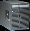
• Keyboard and Mouse • Site Preparation and Installation Product Description The HP VISUALIZE J5000 and J7000 workstations are high-performance systems capable of handling the most complex problems in computational analysis, advanced 3-D design, and electronic circuit design and verification - HP Visualize J7000 | hp Visualize J5000, J7000 workstations service handbook (a4 - Page 19
J5000 and J7000 workstations have the following key features. • CPUs: - J5000 - Two 440 MHz PA-8500 microprocessors, each with 1.5 MB on-chip cache - J7000 - Four 440 MHz PA-8500 microprocessors, each with 1.5 MB on-chip cache • Operating System: Native HP-UX - 32-bit support requires HP-UX version - HP Visualize J7000 | hp Visualize J5000, J7000 workstations service handbook (a4 - Page 20
MHz - Two PCI-4X slots at 3.3V, 66 MHz - One slot for power only • Graphics Cards Currently Supported: - HP VISUALIZE-EG - HP VISUALIZE-FX2 - HP VISUALIZE-FX6 • Monitors Currently Supported: - 19-inch VGA 1600×1200 color monitor (Product Number A4575A) - 21-inch VGA 1600×1200 color monitor (Product - HP Visualize J7000 | hp Visualize J5000, J7000 workstations service handbook (a4 - Page 21
Front Panel Components Front Panel Components This section describes the components that are located on the front panel of the J5000 and J7000 workstations. Figure 1-1 shows the front panel components with the bezel attached. Figure 1-1. Components on the Front Panel with the Bezel Attached Bay for - HP Visualize J7000 | hp Visualize J5000, J7000 workstations service handbook (a4 - Page 22
-hand bay, as well as four hard disk drive brackets in the hard disk drive bays on the right-hand side of the workstation. (As noted earlier, these workstations can support up to four hard disk drives.) In addition, Figure 1-3 shows the location of the two bezel-detach screw holes on the right - HP Visualize J7000 | hp Visualize J5000, J7000 workstations service handbook (a4 - Page 23
located on the left side of the front panel as part of the power switch/LCD assembly. Use the power switch to power the workstation on and off. NOTE The J5000 and J7000 workstations have a "soft power down" feature that shuts the operating system down in a controlled manner when you power off the - HP Visualize J7000 | hp Visualize J5000, J7000 workstations service handbook (a4 - Page 24
Drive(s) The J5000 and J7000 workstations can support up to four hot- supported are: • 9 GB LVD 10K RPM disk drive (Product Number A4997A) • 18 GB LVD 10K RPM disk drive (Product Number A4998A) NOTE The ability to hot plug the hard disk drive(s) requires MirrorDisk/UX (Product Number B5403BA on HP - HP Visualize J7000 | hp Visualize J5000, J7000 workstations service handbook (a4 - Page 25
CD Drive (Optional) As an optional component, the J5000 and J7000 workstations support one 32X CD drive with an ATAPI (IDE) interface (Product Number A5001A). The CD drive is a 5.25-inch, half- height form factor device which connects to the workstation via a 40-pin IDE ribbon cable, a 4-pin audio - HP Visualize J7000 | hp Visualize J5000, J7000 workstations service handbook (a4 - Page 26
Components DDS-3 Tape Drive (Optional) The J5000 and J7000 workstations support either one DDS-3 tape drive or one 3.5-inch LED LED The two colored LEDs on the DDS-3 tape drive indicate different activities or problems that may occur. Figure 1-7 lists the LED codes and their meanings. Figure 1-7. - HP Visualize J7000 | hp Visualize J5000, J7000 workstations service handbook (a4 - Page 27
Components Floppy Disk Drive (Optional) The J5000 and J7000 workstations support either one DDS-3 tape drive or one 3.5-inch A5009A) is a 3.5-inch form factor device with a PC/AT interface. It connects to the workstation via a 34-pin PC/AT ribbon cable and a 4-pin power cable. The floppy disk drive - HP Visualize J7000 | hp Visualize J5000, J7000 workstations service handbook (a4 - Page 28
Information Rear Panel Components Rear Panel Components This section describes the various components located on the rear panel of the J5000 and J7000 workstations. Figure 1-9 shows the locations of these rear panel components. NOTE To maintain FCC/EMI compliance, verify that all cables are fully - HP Visualize J7000 | hp Visualize J5000, J7000 workstations service handbook (a4 - Page 29
power outputs of the power supply, reducing the danger of electric shock while servicing the workstation. Thus, make sure that this power supply interlock thumbscrew is firmly retightened when you finish servicing the workstation, or the power supply may still be disengaged. CAUTION Do not use the - HP Visualize J7000 | hp Visualize J5000, J7000 workstations service handbook (a4 - Page 30
To Send 9 RI Ring Indicator LAN 10/100 BaseT RJ45 Connector The J5000 and J7000 workstations have one built-in, Ethernet IEEE 802.3, RJ45 Twisted Pair connector for 802.3 Connector The 25-pin HP Parallel I/O interface uses Centronics interface protocols to support peripheral devices such as - HP Visualize J7000 | hp Visualize J5000, J7000 workstations service handbook (a4 - Page 31
page 189 for information about connecting SCSI devices to the J5000 and J7000 workstations. CAUTION Do not connect NSE SCSI devices to the LVD SCSI connector, or vice versa, because damage may occur. Currently Hewlett-Packard does not support mixing NSE and LVD devices on the same SCSI bus. NOTE - HP Visualize J7000 | hp Visualize J5000, J7000 workstations service handbook (a4 - Page 32
the power cord into the power cord connector to provide AC power to the workstation. The power cord provides either 15A power to the J5000, or 20A power to the J7000, at 100-120V. The J5000 and J7000 workstations have different power cord connectors and power cords, because of their differing power - HP Visualize J7000 | hp Visualize J5000, J7000 workstations service handbook (a4 - Page 33
on the Rear Panel This subsection describes the following, miscellaneous components that are also located on the rear panel of the J5000 and J7000 workstations: • Security tab • TOC button • I/O slots Security Tab The security tab, which is located at the top of the rear panel, can be used - HP Visualize J7000 | hp Visualize J5000, J7000 workstations service handbook (a4 - Page 34
side panels in order to access these internal components, as well as instructions on how to remove and replace these internal components to service them, see Chapter 4. Internal Components on the Left Side As you face the J5000 and J7000 workstation, the internal components on the left side of the - HP Visualize J7000 | hp Visualize J5000, J7000 workstations service handbook (a4 - Page 35
. In contrast, the J7000 has sixteen memory slots, and memory DIMMs must be installed in pairs of equal size in it. For more information about the sizes of memory DIMMs each workstation supports, as well as the DIMM loading order for each, see the configuration section for "Memory" on page - HP Visualize J7000 | hp Visualize J5000, J7000 workstations service handbook (a4 - Page 36
Fans There are three system board cooling fans in three separate mounting brackets on the front, left side of the J5000 and J7000 workstations. These fans draw air flow from the front of the workstation inward to cool the system board. Internal Components on the Right Side As you face the J5000 and - HP Visualize J7000 | hp Visualize J5000, J7000 workstations service handbook (a4 - Page 37
behind the power supply. Over the center wall of the chassis, the I/O board is attached to the workstation's system board by a flex cable. The I/O board, which is the same in both the J5000 and J7000, has connections to the Serial, LAN, USB, Parallel, SCSI, and audio built-in I/O. See the subsection - HP Visualize J7000 | hp Visualize J5000, J7000 workstations service handbook (a4 - Page 38
Monitors Monitors The J5000 and J7000 workstations currently support the following three HP monitors: • 19-inch J7000 workstations, refer to the HP VISUALIZE J5000/J7000 Site Preparation Guide (Part Number A4978-90220) • Installing J5000 and J7000 workstations, refer to the HP VISUALIZE J5000/J7000 - HP Visualize J7000 | hp Visualize J5000, J7000 workstations service handbook (a4 - Page 39
2 Configuration This chapter provides details about setting up and changing the system configuration for HP VISUALIZE J5000 and J7000 workstations. 35 - HP Visualize J7000 | hp Visualize J5000, J7000 workstations service handbook (a4 - Page 40
- Internal Storage Devices - Memory - I/O Cards - Monitor-Type Selection Workstation Configurations Refer to the HP Workstations Website for a complete list of supported accessories, peripherals, and operating system versions for the J5000 and J7000 workstations. The URL for the Website is: http - HP Visualize J7000 | hp Visualize J5000, J7000 workstations service handbook (a4 - Page 41
Drive (Optional) Configuration The optional CD drive connects to the ATAPI (IDE) interface in the CD drive bay backplane within the J5000 and J7000 workstations via a 40-pin ribbon cable, a 4-pin audio cable, and a 4-pin power cable. No interface addressing is required for the CD drive. However, as - HP Visualize J7000 | hp Visualize J5000, J7000 workstations service handbook (a4 - Page 42
drive. Figure 2-2. DDS-3 Tape Drive NSE SCSI-2 ID/Jumper Settings Bit 0 Bit 1 Bit 2 Term PWR* SCSI Connector Power Connector * Term PWR is not used in HP workstation configurations. 38 Chapter 2 - HP Visualize J7000 | hp Visualize J5000, J7000 workstations service handbook (a4 - Page 43
comes with one 512 MB DIMM as its standard configuration from the factory. Thus, currently the minimum memory configuration for this workstation is 512 MB, and the maximum is 4 GB. DIMMs should be loaded in the order shown in Figure 2-4 on the next page, with slot 0 being - HP Visualize J7000 | hp Visualize J5000, J7000 workstations service handbook (a4 - Page 44
on installing memory. Also note that there is a label on the floor of the workstation's interior showing the J5000's memory loading order. Figure 2-4. Memory Loading Order in the J5000 J7000 Memory Configuration The J7000 workstation has sixteen memory slots, labeled 0A, 0B to 7A, 7B. Memory DIMMs - HP Visualize J7000 | hp Visualize J5000, J7000 workstations service handbook (a4 - Page 45
Configuration Field Replaceable Unit (FRU) Configurations Figure 2-5. Memory Loading Order in the J7000 * J7000 memory must be installed in pairs, and both DIMMs in the pair must be of equal size. Chapter 2 41 - HP Visualize J7000 | hp Visualize J5000, J7000 workstations service handbook (a4 - Page 46
I/O cards. CAUTION The J5000 and J7000 workstations supply about 264 Watts of power to the PCI slots. Do not insert I/O cards that together draw more than 264 Watts, or damage to the workstation may result. NOTE If you install three HP VISUALIZE FX6 graphics cards simultaneously (as in - HP Visualize J7000 | hp Visualize J5000, J7000 workstations service handbook (a4 - Page 47
Configuration Field Replaceable Unit (FRU) Configurations Monitor-Type Selection The J5000 and J7000 workstations currently support the following three HP monitors: • 19-inch (18.3-inch viewable) VGA 1600×1200 color monitor (Product Number A4575A) • 21-inch (19.9-inch viewable) VGA 1600×1200 color - HP Visualize J7000 | hp Visualize J5000, J7000 workstations service handbook (a4 - Page 48
Configuration Field Replaceable Unit (FRU) Configurations 44 Chapter 2 - HP Visualize J7000 | hp Visualize J5000, J7000 workstations service handbook (a4 - Page 49
3 Troubleshooting This chapter provides information about isolating a failing component, known as a Field Replaceable Unit (FRU), in HP VISUALIZE J5000 and J7000 workstations. 45 - HP Visualize J7000 | hp Visualize J5000, J7000 workstations service handbook (a4 - Page 50
• Fan Problems Introduction to Troubleshooting To troubleshoot HP VISUALIZE J5000 and J7000 workstations, you must be familiar with the HP-UX operating system and be able to start and stop processes. You should also be familiar with the boot ROM diagnostics, ISL diagnostics, and the Support Tools - HP Visualize J7000 | hp Visualize J5000, J7000 workstations service handbook (a4 - Page 51
Figure 3-1. Main Flowchart for Troubleshooting Troubleshooting Flowcharts for Troubleshooting Chapter 3 47 - HP Visualize J7000 | hp Visualize J5000, J7000 workstations service handbook (a4 - Page 52
Troubleshooting Flowcharts for Troubleshooting Figure 3-2. Console Troubleshooting Flowchart 48 Chapter 3 - HP Visualize J7000 | hp Visualize J5000, J7000 workstations service handbook (a4 - Page 53
Troubleshooting Flowcharts for Troubleshooting Figure 3-3. Bootable Device Troubleshooting Flowchart Chapter 3 49 - HP Visualize J7000 | hp Visualize J5000, J7000 workstations service handbook (a4 - Page 54
Troubleshooting Flowcharts for Troubleshooting Figure 3-4. HP-UX Troubleshooting Flowchart 50 Chapter 3 - HP Visualize J7000 | hp Visualize J5000, J7000 workstations service handbook (a4 - Page 55
Troubleshooting Dealing with a Boot Failure Dealing with a Boot Failure To start this workstation from an operating system alternate version of the HP-UX operating system. For example, if the usual kernel (/stand/vmunix) on the root disk has become corrupted, boot the workstation from the backup - HP Visualize J7000 | hp Visualize J5000, J7000 workstations service handbook (a4 - Page 56
Troubleshooting Dealing with a Boot Failure Searching for Bootable Media To list all boot flags, HPMC error information, and operating system initialization data. Boot Command Notations The boot command supports the following two notations: • Mnemonic • Path number Type help scsi or help lan for more - HP Visualize J7000 | hp Visualize J5000, J7000 workstations service handbook (a4 - Page 57
by a previous search command. Supported Boot Paths SCSI devices are bootable when connected to any SCSI port on the system. Diskless workstations can only boot from the to execute diagnostic and utility programs from a boot device when HP-UX does not load. The ISL program is the first program - HP Visualize J7000 | hp Visualize J5000, J7000 workstations service handbook (a4 - Page 58
the Service Menu's pim, pdt, and ChassisCodes commands to get additional information about the failure. The FRU column in Table 3-1 shows messages printed on the LCD that refer to system FRUs. All codes are listed in numeric order. Memory Failures The J5000 and J7000 workstations require special - HP Visualize J7000 | hp Visualize J5000, J7000 workstations service handbook (a4 - Page 59
Troubleshooting Identifying LCD-Indicated Conditions Chassis Codes Table 3-1 lists all of the chassis codes for the J5000 and J7000 workstations. Table 3-1. Chassis Codes for J5000 and J7000 Workstations Ostat FLT FLT FLT FLT FLT FLT FLT FLT FLT FLT FLT FLT FLT FLT FLT FLT FLT Code FRU 1n01 1n02 - HP Visualize J7000 | hp Visualize J5000, J7000 workstations service handbook (a4 - Page 60
Troubleshooting Identifying LCD-Indicated Conditions Table 3-1. Chassis Codes for J5000 and J7000 Workstations Ostat FLT and logical unit self-test. CPUn branch test CPU n is starting its branch instruction self-test. CPUn arith cond CPU n is starting its arthimetic condition self-test. - HP Visualize J7000 | hp Visualize J5000, J7000 workstations service handbook (a4 - Page 61
Troubleshooting Identifying LCD-Indicated Conditions Table 3-1. Chassis Codes for J5000 and J7000 Workstations Ostat TST floating-point register self-test. CPUn fpu inst CPU n is starting its floating-point instruction self-test. CPUn fpu traps CPU n is starting its floating-point trap self- - HP Visualize J7000 | hp Visualize J5000, J7000 workstations service handbook (a4 - Page 62
Troubleshooting Identifying LCD-Indicated Conditions Table 3-1. Chassis Codes for J5000 and J7000 Workstations word. monarchn selftst Monarch CPU n failed self-test. CPUn icache RAM CPU n is starting its instruction cache RAM self-test. CPUn ic ld d err CPU n detected a data error during data - HP Visualize J7000 | hp Visualize J5000, J7000 workstations service handbook (a4 - Page 63
Troubleshooting Identifying LCD-Indicated Conditions Table 3-1. Chassis Codes for J5000 and J7000 Workstations Ostat TST TST FLT TST FLT INI TST INI FLT TST INI FLT WRN FLT INI INI WRN FLT FLT WRN FLT Code FRU 2n80 - HP Visualize J7000 | hp Visualize J5000, J7000 workstations service handbook (a4 - Page 64
Troubleshooting Identifying LCD-Indicated Conditions Table 3-1. Chassis Codes for J5000 and J7000 Workstations Ostat INI FLT WRN TST WRN FLT TST WRN FLT INI TST INI FLT FLT TST INI FLT FLT FLT FLT Code FRU 3n07 SYS - HP Visualize J7000 | hp Visualize J5000, J7000 workstations service handbook (a4 - Page 65
Troubleshooting Identifying LCD-Indicated Conditions Table 3-1. Chassis Codes for J5000 and J7000 Workstations Ostat and logic unit self-test. CPUn lst branch CPU n is re-executing its branch instruction self-test. CPUn lst arth cd CPU n is re-executing its arithmetic conditions self- - HP Visualize J7000 | hp Visualize J5000, J7000 workstations service handbook (a4 - Page 66
Troubleshooting Identifying LCD-Indicated Conditions Table 3-1. Chassis Codes for J5000 and J7000 Workstations Ostat TST DIMM 7013 DIMM 7016 DIMM Message Description CPUn icache miss CPU n is starting its instruction cache miss self-test. CPUn dcache miss CPU n is starting its data cache miss - HP Visualize J7000 | hp Visualize J5000, J7000 workstations service handbook (a4 - Page 67
Troubleshooting Identifying LCD-Indicated Conditions Table 3-1. Chassis Codes for J5000 and J7000 Workstations Ostat WRN FLT TST TST FLT TST INI INI TST type. SPD fatal error SPD detected an unexpected, fatal error. add HP DIMM type New HP manufactured DIMM type added to tables. Chapter 3 63 - HP Visualize J7000 | hp Visualize J5000, J7000 workstations service handbook (a4 - Page 68
Troubleshooting Identifying LCD-Indicated Conditions Table 3-1. Chassis Codes for J5000 and J7000 Workstations Ostat INI FLT FLT INI INI SYS BD 7305 SYS BD 7306 SYS BD 7307 SYS BD Message Description non-HP DIMM type New non-HP DIMM type added to tables (use at own risk). DIMM table full The - HP Visualize J7000 | hp Visualize J5000, J7000 workstations service handbook (a4 - Page 69
Troubleshooting Identifying LCD-Indicated Conditions Table 3-1. Chassis Codes for J5000 and J7000 Workstations Ostat FLT FLT FLT INI TST TST INI WRN FLT TST WRN init x% Memory initialization is x% complete. repeat dest test Re-execute destructive test for hardware troubleshooting. Chapter 3 65 - HP Visualize J7000 | hp Visualize J5000, J7000 workstations service handbook (a4 - Page 70
Troubleshooting Identifying LCD-Indicated Conditions Table 3-1. Chassis Codes for J5000 and J7000 Workstations Ostat FLT FLT FLT FLT FLT FLT FLT FLT FLT FLT FLT FLT FLT FLT FLT FLT FLT FLT FLT Code FRU 760D DIMM 7610 - HP Visualize J7000 | hp Visualize J5000, J7000 workstations service handbook (a4 - Page 71
Troubleshooting Identifying LCD-Indicated Conditions Table 3-1. Chassis Codes for J5000 and J7000 Workstations Ostat FLT FLT FLT FLT FLT FLT FLT FLT FLT FLT FLT FLT FLT FLT FLT FLT FLT FLT FLT FLT WRN Code FRU 7843 - HP Visualize J7000 | hp Visualize J5000, J7000 workstations service handbook (a4 - Page 72
Troubleshooting Identifying LCD-Indicated Conditions Table 3-1. Chassis Codes for J5000 and J7000 Workstations Ostat WRN WRN WRN WRN WRN WRN INI INI INI INI INI WRN FLT WRN FLT WRN FLT INI FLT INI FLT INI INI FLT - HP Visualize J7000 | hp Visualize J5000, J7000 workstations service handbook (a4 - Page 73
Troubleshooting Identifying LCD-Indicated Conditions Table 3-1. Chassis Codes for J5000 and J7000 Workstations Ostat INI FLT device requested invalid memory type. PCI max bus dpth PCI bus depth exceeded maximum supported depth. PCI dev not cnfg Unable to configure PCI device. dev tree ovrflow - HP Visualize J7000 | hp Visualize J5000, J7000 workstations service handbook (a4 - Page 74
Troubleshooting Identifying LCD-Indicated Conditions Table 3-1. Chassis Codes for J5000 and J7000 Workstations Ostat INI INI INI WRN INI WRN INI WRN INI WRN INI WRN FLT WRN WRN FLT WRN WRN INI INI Code FRU 916s EXT - HP Visualize J7000 | hp Visualize J5000, J7000 workstations service handbook (a4 - Page 75
Troubleshooting Identifying LCD-Indicated Conditions Table 3-1. Chassis Codes for J5000 and J7000 Workstations Ostat INI INI FLT INI INI INI INI INI INI INI WRN FLT WRN WRN WRN WRN WRN INI INI FLT WRN Code FRU C30C - HP Visualize J7000 | hp Visualize J5000, J7000 workstations service handbook (a4 - Page 76
Troubleshooting Identifying LCD-Indicated Conditions Table 3-1. Chassis Codes for J5000 and J7000 Workstations Ostat WRN TST INI WRN INI INI WRN WRN WRN WRN WRN WRN WRN INI WRN WRN WRN Code C64F C68s C68s C68s C740 C780 - HP Visualize J7000 | hp Visualize J5000, J7000 workstations service handbook (a4 - Page 77
Troubleshooting Identifying LCD-Indicated Conditions Table 3-1. Chassis Codes for J5000 and J7000 Workstations Ostat WRN WRN LPMC handler. The handler should log the error and return to normal operation. An instruction cache parity error caused the LPMC. dcache LPMC err A data cache parity/ECC - HP Visualize J7000 | hp Visualize J5000, J7000 workstations service handbook (a4 - Page 78
Troubleshooting Identifying LCD-Indicated Conditions Table 3-1. Chassis Codes for J5000 and J7000 Workstations Ostat FLT FLT OFF OFF OFF OFF OFF OFF OFF OFF OFF OFF OFF OFF OFF OFF OFF OFF OFF OFF OFF Code FRU CB99 - HP Visualize J7000 | hp Visualize J5000, J7000 workstations service handbook (a4 - Page 79
Troubleshooting Identifying LCD-Indicated Conditions Table 3-1. Chassis Codes for J5000 and J7000 Workstations Ostat OFF Code FRU CBC6 IO BD OFF CBC8 IO BD OFF CBCA IO BD OFF CBCC IO BD OFF CBCE IO BD OFF CBD0 - HP Visualize J7000 | hp Visualize J5000, J7000 workstations service handbook (a4 - Page 80
Troubleshooting Identifying LCD-Indicated Conditions Table 3-1. Chassis Codes for J5000 and J7000 Workstations Ostat OFF OFF OFF OFF FLT FLT FLT FLT FLT FLT WRN FLT FLT FLT FLT FLT Code FRU CBE6 SYS BD CBE7 CBE8 IO - HP Visualize J7000 | hp Visualize J5000, J7000 workstations service handbook (a4 - Page 81
Troubleshooting Identifying LCD-Indicated Conditions Table 3-1. Chassis Codes for J5000 and J7000 Workstations Ostat INI INI INI INI INI TST WRN INI INI WRN FLT WRN Code FRU CC0n SYS BD CC1n SYS BD CC2n SYS BD CC3n - HP Visualize J7000 | hp Visualize J5000, J7000 workstations service handbook (a4 - Page 82
man cstm [Enter] man mstm [Enter] man xstm [Enter] For information on the enhanced online diagnostics, see the Support Media User's Manual (HP Part Number B3782-90176). To access the Support Tools Manager, perform the following steps: 1. In a terminal window, type the following at the # prompt to - HP Visualize J7000 | hp Visualize J5000, J7000 workstations service handbook (a4 - Page 83
Troubleshooting Running ODE-Based Diagnostics Running ODE-Based Diagnostics The Offline Diagnostic Environment (ODE) consists of diagnostic modules for testing and verifying system operation. ODE provides - HP Visualize J7000 | hp Visualize J5000, J7000 workstations service handbook (a4 - Page 84
Troubleshooting Fan Problems Fan Problems A chassis code which indicates that a fan has failed (FLT D01n) or is running too slowly (WRN D02n) within a J5000 or J7000 workstation specifies the fan number, n. Table 3-2 maps these fan numbers to the physical locations of the fans within each - HP Visualize J7000 | hp Visualize J5000, J7000 workstations service handbook (a4 - Page 85
4 Field Replaceable Units (FRUs) This chapter lists the Field Replaceable Units (FRUs) for the HP VISUALIZE J5000 and J7000 workstations. This chapter then provides procedures for removing and replacing the FRUs in the workstations. 81 - HP Visualize J7000 | hp Visualize J5000, J7000 workstations service handbook (a4 - Page 86
Storage Devices - Memory DIMMs - DC/DC Converter Units and Air Dividers (J7000 Only) - System Board Tray Assembly - Battery on System Board - System Board procedures in this chapter, you must power off the workstation and unplug the workstation power cord from the AC power outlet. NOTE To - HP Visualize J7000 | hp Visualize J5000, J7000 workstations service handbook (a4 - Page 87
nonexchange part numbers - you may discard them. The following Tables 4-1 and 4-2 list the exchange part numbers for the J5000 and the J7000 workstation, respectively. Table 4-1. J5000 Exchange Part Numbers Part Number A4978-69010 A4978-69001 A4978-69020 A3862-69001 A3863-69001 A1658-69027 A1658 - HP Visualize J7000 | hp Visualize J5000, J7000 workstations service handbook (a4 - Page 88
GB 10K RPM SCSI DDS-3 tape drive 12 GB The following Tables 4-3 and 4-4 list the nonexchange part numbers for the J5000 and the J7000 workstation, respectively. Table 4-3. J5000 Nonexchange Part Numbers Part Number A4978-86007 A4978-62004 A4978-84005 A4978-00039 A4978-62025 A4978-62005 A4978-89006 - HP Visualize J7000 | hp Visualize J5000, J7000 workstations service handbook (a4 - Page 89
Field Replaceable Units (FRUs) Exchange and Nonexchange Part Numbers Table 4-3. J5000 Nonexchange Part Numbers Part Number 0361-1315 5063-4513 A4978-40011 A4978-62003 A4986-40007 A4978-40013 A4978-00042 A4978-63009 A4978-63005 A4978-63004 5182-1857 A4978-89005 A4978-00073 A4983-60101 A4983-60111 - HP Visualize J7000 | hp Visualize J5000, J7000 workstations service handbook (a4 - Page 90
Field Replaceable Units (FRUs) Exchange and Nonexchange Part Numbers Table 4-4. J7000 Non-Exchange Part Numbers Part Number A4978-86007 A4978-62004 A4978-84011 A4978-00039 A4978-62025 A4978-62005 A4978-89006 A4978-62006 D4385-60001 A4978- - HP Visualize J7000 | hp Visualize J5000, J7000 workstations service handbook (a4 - Page 91
Field Replaceable Units (FRUs) Exchange and Nonexchange Part Numbers Table 4-4. J7000 Non-Exchange Part Numbers Part Number A4978-63005 A4978-63004 5182-1857 A4978-89005 A4978-00073 A4983-60101 A4983-60111 A4983-60401 A4983-60403 A4983- - HP Visualize J7000 | hp Visualize J5000, J7000 workstations service handbook (a4 - Page 92
) FRU Removal and Replacement FRU Removal and Replacement The procedures in this section describe how to remove and replace J5000 and J7000 workstation FRUs. Observe the electrostatic discharge (ESD) precautions and the prerequisites for removing and replacing FRUs in the next two subsections, as - HP Visualize J7000 | hp Visualize J5000, J7000 workstations service handbook (a4 - Page 93
peripheral devices from AC power outlets. 3. Attach the static-grounding wrist strap by following the instructions on the package. Attach the sticky end of the wrist strap to bare metal on the rear panel of the workstation. NOTE To make access to the internal FRUs easier, you may want to place the - HP Visualize J7000 | hp Visualize J5000, J7000 workstations service handbook (a4 - Page 94
the FRU removal and replacement procedures in this chapter. Figure 4-1. Exploded View of the J5000 and J7000 Workstation Flex cable Top panel retainer Flex cable DC/DC converter units and tie-downs for J7000 Left side panel DDS-3/floppy EMI cover Chassis I/O board CD EMI cover Right side panel - HP Visualize J7000 | hp Visualize J5000, J7000 workstations service handbook (a4 - Page 95
Field Replaceable Units (FRUs) FRU Removal and Replacement Front Bezel and Outer Panels This section describes how to remove and replace the J5000 and J7000 workstation's front bezel, as well as the top and the two side outer panels. Note that you can perform certain operations, like removing and - HP Visualize J7000 | hp Visualize J5000, J7000 workstations service handbook (a4 - Page 96
front bezel, do the following: 1. Align the three metal bezel hooks into the three bezel hinge holes along the left edge of the workstation's front panel. Figure 4-3. Locations of the Bezel Hinge Holes Bezel hinge holes 2. Press inward while rotating the front bezel counterclockwise. 3. Press firmly - HP Visualize J7000 | hp Visualize J5000, J7000 workstations service handbook (a4 - Page 97
the Top Panel To remove the top panel, do the following: 1. Remove the two thumbscrews in the top left and right corners of the workstation's rear panel. NOTE The upper-left thumbscrew has a power supply interlock. Removing this thumbscrew disengages all power outputs of the power supply, reducing - HP Visualize J7000 | hp Visualize J5000, J7000 workstations service handbook (a4 - Page 98
do the following: 1. Remove the top panel, as explained in the previous procedure. 2. Remove each side panel by tipping it out and away from the workstation, as shown in Figure 4-4 on the previous page. To replace the side panels, see "Replacing the Top and Side Panels" below. Replacing the Top and - HP Visualize J7000 | hp Visualize J5000, J7000 workstations service handbook (a4 - Page 99
Field Replaceable Units (FRUs) FRU Removal and Replacement Power Switch/LCD Assembly This section describes how to remove and replace the J5000 and J7000 workstation's power switch/LCD assembly, which is located on the front panel. Removing the Power Switch/LCD Assembly To remove the power switch/ - HP Visualize J7000 | hp Visualize J5000, J7000 workstations service handbook (a4 - Page 100
J5000 and J7000 workstation's internal HP-UX 10.20, or B2491BA on HP-UX 11.0). If MirrorDisk/UX is installed on the workstation, you do not need to power down the workstation nor unplug the workstation instructions. Removing a Hard Disk Drive: 1. Open the right door of the bezel on the workstation - HP Visualize J7000 | hp Visualize J5000, J7000 workstations service handbook (a4 - Page 101
hot-plugging the hard disk drive, wait 30 seconds for the drive to spin down. 5. Carefully slide the hard disk drive out of the chassis guide rails while grasping the body with the other hand. CAUTION Dropping the hard disk drive can cause severe damage to the drive hardware. 6. To remove - HP Visualize J7000 | hp Visualize J5000, J7000 workstations service handbook (a4 - Page 102
Drive Configuration" on page 36 for information about configuring a hard disk drive for installation. 1. Open the right door of the bezel on the workstation's front panel. 2. Perform the previous removal procedure in reverse order. NOTE To verify a good connection with the SCA hard disk interface - HP Visualize J7000 | hp Visualize J5000, J7000 workstations service handbook (a4 - Page 103
empty CD drive bay: a. Remove the two T-15 Torx screws securing the CD drive bracket to the front panel of the workstation. b. Slide the CD drive bracket out of the chassis guide rails. c. Remove the filler panel from the CD drive bracket as shown in Figure 4-10 on the next page. Chapter - HP Visualize J7000 | hp Visualize J5000, J7000 workstations service handbook (a4 - Page 104
assembly halfway into the CD drive bay. 6. From the top of the workstation, reach behind the CD drive and connect the audio cable, power cable, and to avoid damage during the next step. 7. From the front of the workstation, push the CD drive bracket assembly to seat flush against the front panel, - HP Visualize J7000 | hp Visualize J5000, J7000 workstations service handbook (a4 - Page 105
screws securing the DDS-3 tape drive to the front panel of the workstation chassis. Figure 4-12. Front Panel Screws T-15 Torx screw T-15 Torx screw 3. Slide the DDS-3 tape/floppy disk drive bracket assembly out of the chassis guide rails. Disconnect the the power and ribbon cables from the DDS - HP Visualize J7000 | hp Visualize J5000, J7000 workstations service handbook (a4 - Page 106
Remove the two T-15 Torx screws securing the DDS-3 tape/floppy disk drive bracket to the front panel of the workstation. b. Slide the DDS-3 tape/floppy disk drive bracket out of the chassis guide rails. c. Remove the filler panels from the DDS-3 tape/floppy disk drive bracket as shown in Figure 4-13 - HP Visualize J7000 | hp Visualize J5000, J7000 workstations service handbook (a4 - Page 107
(FRUs) FRU Removal and Replacement 7. Insert and tighten the two T-15 Torx screws to secure the DDS-3 tape drive to the front panel of the workstation, as shown in Figure 4-12 on page 101. 8. Replace the DDS-3/floppy disk drive EMI cover and top panel. 9. Replace the front panel bezel. 10 - HP Visualize J7000 | hp Visualize J5000, J7000 workstations service handbook (a4 - Page 108
Remove the two T-15 Torx screws securing the DDS-3 tape/floppy disk drive bracket to the front panel of the workstation. b. Slide the DDS-3 tape/floppy disk drive bracket out of the chassis guide rails. c. Remove the filler panels from the DDS-3 tape/floppy disk drive bracket as shown in Figure 4-15 - HP Visualize J7000 | hp Visualize J5000, J7000 workstations service handbook (a4 - Page 109
flush against the front panel. 8. Insert and tighten the two T-15 Torx screws to secure the floppy disk drive to the front panel of the workstation. 9. Replace the DDS-3/floppy disk drive EMI cover and top panel. 10.Replace the front panel bezel. 11.After rebooting, use SAM to confirm that - HP Visualize J7000 | hp Visualize J5000, J7000 workstations service handbook (a4 - Page 110
Current Monitor Configuration" on page 162 in Chapter 5 to determine the current memory configuration of the workstation. 2. Remove the top panel and the left side panel of the workstation. 3. If this is a J7000 workstation, remove the four screws from the front air divider on the left side of the - HP Visualize J7000 | hp Visualize J5000, J7000 workstations service handbook (a4 - Page 111
as the DIMM is inserted. 9. If this is a J7000 workstation, replace the front air divider and the four T-15 Torx screws securing the front air divider. 10 replaced a faulty DIMM, use the pdt clear command in the Service Menu of the Boot Console Handler. Answer y (yes) to the prompt Continue? (Y/N) >. - HP Visualize J7000 | hp Visualize J5000, J7000 workstations service handbook (a4 - Page 112
Units and Air Dividers To remove the DC/DC converter units and air dividers, do the following: 1. Remove the J7000 workstation's top panel and left side panel. 2. On the left side of the workstation, remove the four T-15 Torx screws from the front air divider as shown in Figure 4-18, and then remove - HP Visualize J7000 | hp Visualize J5000, J7000 workstations service handbook (a4 - Page 113
the DC/DC Converter Units and Air Dividers To replace the DC/DC converter units and air dividers, do the following: 1. Remove the J7000 workstation's top panel and left side panel. 2. Perform the previous removal procedure in reverse order. NOTE The two DC/DC converter units are interchangeable - HP Visualize J7000 | hp Visualize J5000, J7000 workstations service handbook (a4 - Page 114
System Board Tray Assembly The system board in the J5000 and J7000 workstation is mounted on a tray. The following procedures describe how to The flex cable retainer and the flex cable are located at the top of the workstation, near the rear. The flex cable straddles the center wall of the chassis, - HP Visualize J7000 | hp Visualize J5000, J7000 workstations service handbook (a4 - Page 115
in Figure 4-22. Figure 4-22. Removing the Bus Bar Shield Bus bar shield 4. Remove either the four bus bar thumbscrews on the J5000 workstation, or the five bus bar thumbscrews on the J7000. Figure 4-23 shows these thumbscrews on the J5000 workstation. Figure 4-23. Bus Bar Thumbscrews Chapter 4 111 - HP Visualize J7000 | hp Visualize J5000, J7000 workstations service handbook (a4 - Page 116
) FRU Removal and Replacement 5. If you are removing the system board from a J7000 workstation, you must also remove the front and rear air dividers and the two DC/DC converter units that are attached to the J7000's system board. To remove these components, follow the removal procedures in "DC/DC - HP Visualize J7000 | hp Visualize J5000, J7000 workstations service handbook (a4 - Page 117
to the rear panel of the workstation, as shown in Figure 4-25 above. CAUTION The J7000 workstation's system board has four turbocoolers mounted the workstation. The sheet metal hooks on the workstation's center wall will disengage from the holes on the system board tray assembly. 11.Support the - HP Visualize J7000 | hp Visualize J5000, J7000 workstations service handbook (a4 - Page 118
power switch/LCD assembly to the system board. Refer to Figures 4-24 and 4-25 on the previous two pages. You should also pull the J7000 workstation's fan cables through the system board's tray handle for clearance. 7. Connect the flex cable to the system board and I/O board connectors as shown in - HP Visualize J7000 | hp Visualize J5000, J7000 workstations service handbook (a4 - Page 119
bus bars to the system board with either the four bus bar thumbscrews on the J5000 workstation, or the five bus bar thumbscrews on the J7000. Figure 4-27 shows these thumbscrews on the J5000 workstation. NOTE Failure to sufficiently tighten the bus bar thumbscrews will cause the power supply to - HP Visualize J7000 | hp Visualize J5000, J7000 workstations service handbook (a4 - Page 120
procedures in "Memory DIMMs" on page 106. 12.If you are replacing the system board in a J7000 workstation, you must also replace the two DC/DC converter units that are attached to the J7000's system board, as well as the front and rear air dividers. To replace these components, follow the - HP Visualize J7000 | hp Visualize J5000, J7000 workstations service handbook (a4 - Page 121
Fan To remove a system board cooling fan, do the following: 1. Remove the top panel and the left side panel of the workstation. 2. If you are removing a system board cooling fan from a J7000 workstation, you must also remove the front and rear air dividers and the two DC/DC converter units that are - HP Visualize J7000 | hp Visualize J5000, J7000 workstations service handbook (a4 - Page 122
is attached to the inner fan wall by four plastic rivets. Using your index finger, press on each rivet from the front side of the workstation to remove the back side of the plastic rivets from the rivet inserts, as shown in Figure 4-31. Figure 4-31. Removing a Rivet 5. Push the fan - HP Visualize J7000 | hp Visualize J5000, J7000 workstations service handbook (a4 - Page 123
so that the air flow arrow on the fan, as shown in Figure 4-32, points toward the rear of the workstation. Figure 4-32. Fan Air Flow Arrow 2. Locate the fan cable's guide slot in the sheet metal and thread the cable accordingly, as shown in Figure 4-33. Figure 4-33. Threading the Fan - HP Visualize J7000 | hp Visualize J5000, J7000 workstations service handbook (a4 - Page 124
FRU Removal and Replacement 4. Guide the insertion barrel into the fan fastener hole from the center of the workstation. Press the rivet pin system board cooling fan in a J7000 workstation, you must also replace the two DC/DC converter units that are attached to the J7000's system board, as well as - HP Visualize J7000 | hp Visualize J5000, J7000 workstations service handbook (a4 - Page 125
) FRU Removal and Replacement I/O Cards The J5000 and J7000 workstations have 64-bit slots for PCI (Peripheral Connect Interface) I/O cards. As you face the front of the workstation, the I/O slots are located on the I/O board on the right side of the workstation. There are five PCI-2X slots, two PCI - HP Visualize J7000 | hp Visualize J5000, J7000 workstations service handbook (a4 - Page 126
Card To replace an I/O card, do the following: 1. Remove the top panel and the right side panel of the workstation. 2. Locate the I/O board and its I/O slots on the right side of the workstation, as shown in Figure 4-34 on the previous page. Note that the I/O board extends up behind the power supply - HP Visualize J7000 | hp Visualize J5000, J7000 workstations service handbook (a4 - Page 127
for power only. CAUTION The J5000 and J7000 workstations supply about 264 Watts of power to the PCI slots. Do not insert I/O cards that together draw more than 264 Watts, or damage to the workstation may result. NOTE If you install three HP VISUALIZE FX6 graphics cards simultaneously (as in the - HP Visualize J7000 | hp Visualize J5000, J7000 workstations service handbook (a4 - Page 128
the filler plate for later use. 6. Insert the I/O card in the card guides and press the card firmly and evenly into the I/O slot connector until the to the I/O slot. 8. Replace the PCI retainer clip. 9. Replace the workstation's top and right side panels. 10. After rebooting, use SAM to confirm - HP Visualize J7000 | hp Visualize J5000, J7000 workstations service handbook (a4 - Page 129
Field Replaceable Units (FRUs) FRU Removal and Replacement Battery on I/O Board The battery in the J5000 and J7000 workstations is contained within the real-time clock module on the I/O board. This section describes how to remove and replace the real-time clock module containing - HP Visualize J7000 | hp Visualize J5000, J7000 workstations service handbook (a4 - Page 130
. Note the polarity dot which is silk-screened on the component side of the circuit board. CAUTION Dispose of used batteries according to the manufacturer's instructions. 126 Chapter 4 - HP Visualize J7000 | hp Visualize J5000, J7000 workstations service handbook (a4 - Page 131
, follow the replacement procedures in "I/O Cards" on page 121. 3. Replace the PCI retainer clip. 4. Replace the top panel and the right side panel of the workstation. Chapter 4 127 - HP Visualize J7000 | hp Visualize J5000, J7000 workstations service handbook (a4 - Page 132
Units (FRUs) FRU Removal and Replacement Power Supply This section describes how to remove and replace the power supply in the J5000 and J7000 workstations. As you face the workstation, the power supply is on the right side. NOTE If the LCD displays an error message that relates to one of the - HP Visualize J7000 | hp Visualize J5000, J7000 workstations service handbook (a4 - Page 133
(FRUs) FRU Removal and Replacement 4. Remove either the four bus bar thumbscrews on the J5000 workstation, or the five bus bar thumbscrews on the J7000. Figure 4-42 shows these thumbscrews on the J5000 workstation. Figure 4-42. Bus Bar Thumbscrews 5. Remove the two T-15 Torx screws that secure the - HP Visualize J7000 | hp Visualize J5000, J7000 workstations service handbook (a4 - Page 134
4-44 above. CAUTION The power supplies for the J5000 and J7000 weigh approximately 14 pounds and 17 pounds, respectively. Be prepared top panel and the right side panel of the workstation. 2. Inspect the underside of the gold plated bus guide rails, as shown in Figure 4-45 on the next page. 130 - HP Visualize J7000 | hp Visualize J5000, J7000 workstations service handbook (a4 - Page 135
with both hands and align the power supply with the guide rails. Slide the power supply forward on the guide rails to seat it in the I/O board connectors. the J5000 workstation, or the five bus bar thumbscrews on the J7000. Figure 4-46 shows these thumbscrews on the J5000 workstation. NOTE Failure - HP Visualize J7000 | hp Visualize J5000, J7000 workstations service handbook (a4 - Page 136
Power Supply T-15 Torx screw T-15 Torx screws 9. Replace the PCI retainer clip. 10. Replace the top panel and the right side panel of the workstation. 132 Chapter 4 - HP Visualize J7000 | hp Visualize J5000, J7000 workstations service handbook (a4 - Page 137
This section describes how to remove and replace the I/O board in J5000 and J7000 workstations. Removing the I/O Board To remove the I/O board, do the following: 1. Remove the top panel and the right side panel from the workstation. 2. Remove the PCI retainer clip by pressing down on the thumb tab - HP Visualize J7000 | hp Visualize J5000, J7000 workstations service handbook (a4 - Page 138
• Power cable • CD drive power cable and audio cable 7. Remove the two T-15 Torx screws that secure the I/O board to the rear panel of the workstation, as shown in Figure 4-51 on the next page. 134 Chapter 4 - HP Visualize J7000 | hp Visualize J5000, J7000 workstations service handbook (a4 - Page 139
. 2. Perform the previous removal steps in reverse. NOTE For correct installation, you must slide the I/O board to the rear of the workstation chassis until the EMI (electromagnetic interference) fingers have been compressed. During installation, it is also very easy to miss some of the keyhole - HP Visualize J7000 | hp Visualize J5000, J7000 workstations service handbook (a4 - Page 140
hard disk interface (also known as the backplane board), which is mounted on the back of the hard disk drive bays in the J5000 and J7000 workstations. Removing the SCA Hard Disk Interface To remove the SCA hard disk interface, do the following: 1. Disconnect all hard disk drives from the front panel - HP Visualize J7000 | hp Visualize J5000, J7000 workstations service handbook (a4 - Page 141
SCA Hard Disk Interface To replace the SCA hard disk interface, do the following: 1. Remove the top panel and the right side panel from the workstation. 2. Perform the previous removal steps in reverse. Chapter 4 137 - HP Visualize J7000 | hp Visualize J5000, J7000 workstations service handbook (a4 - Page 142
mounting bracket in the bottom of the front, right side of the workstation. Removing the I/O Cooling Fan To remove the I/O cooling fan, do the following : 1. Remove the top panel and the right side panel from the workstation. 2. Remove the PCI retainer clip by pressing down on the thumb tab - HP Visualize J7000 | hp Visualize J5000, J7000 workstations service handbook (a4 - Page 143
Field Replaceable Units (FRUs) FRU Removal and Replacement 6. Pull on the fan/speaker mounting bracket tab that is closest to the internal chassis wall, as shown in Figure 4-55. Figure 4-55. Loosening the Fan/Speaker Mounting Bracket 7. Rotate and tilt the mounting bracket to remove it from the - HP Visualize J7000 | hp Visualize J5000, J7000 workstations service handbook (a4 - Page 144
the fan in the fan/speaker mounting bracket. 2. Position the fan so that the flow arrow points towards the I/O card guide rails. 3. To avoid interference with the I/O card guide rails, you must thread the fan cable through the plastic slot adjacent to the release tab for the fan/speaker mounting - HP Visualize J7000 | hp Visualize J5000, J7000 workstations service handbook (a4 - Page 145
following the replacement procedures in "I/O Cards" on page 121. 8. Replace the PCI retainer clip. 9. Replace the top panel and the right side panel of the workstation. Chapter 4 141 - HP Visualize J7000 | hp Visualize J5000, J7000 workstations service handbook (a4 - Page 146
to remove and replace the speaker, which is located in the fan/speaker mounting bracket in the bottom of the front, right side of the workstation. Removing the Speaker To remove the speaker, do the following: 1. Remove the top panel and the right side panel. 2. Remove the PCI retainer clip by - HP Visualize J7000 | hp Visualize J5000, J7000 workstations service handbook (a4 - Page 147
Field Replaceable Units (FRUs) FRU Removal and Replacement 6. Pull on the fan/speaker mounting bracket tab that is closest to the internal chassis wall, as shown in Figure 4-62. Figure 4-62. Loosening the Fan/Speaker Mounting Bracket 7. Rotate and tilt the mounting bracket to remove it from the - HP Visualize J7000 | hp Visualize J5000, J7000 workstations service handbook (a4 - Page 148
Speaker To replace the speaker, do the following: 1. Reinsert the speaker in the fan/speaker mounting bracket. 2. To avoid interference with the I/O card guide rails, you must thread the speaker and fan cables through the plastic slot adjacent to the release tab for the fan/speaker mounting bracket - HP Visualize J7000 | hp Visualize J5000, J7000 workstations service handbook (a4 - Page 149
following the replacement procedures in "I/O Cards" on page 121. 7. Replace the PCI retainer clip. 8. Replace the top panel and the right side panel of the workstation. Chapter 4 145 - HP Visualize J7000 | hp Visualize J5000, J7000 workstations service handbook (a4 - Page 150
Field Replaceable Units (FRUs) FRU Removal and Replacement 146 Chapter 4 - HP Visualize J7000 | hp Visualize J5000, J7000 workstations service handbook (a4 - Page 151
5 Boot Console Handler This chapter explains how to use the Boot Console Handler, which provides an interactive environment after the power-on sequence in HP VISUALIZE J5000 and J7000 workstations. 147 - HP Visualize J7000 | hp Visualize J5000, J7000 workstations service handbook (a4 - Page 152
: • Boot Console Handler Features • Accessing the Boot Console Handler • Boot Console Menus • Booting the Workstation • Searching for Bootable Media • Resetting the Workstation • Displaying and Setting Paths • Displaying and Setting the Monitor Type • Displaying the Current Memory Configuration - HP Visualize J7000 | hp Visualize J5000, J7000 workstations service handbook (a4 - Page 153
Handler Features There are times when you want to interact directly with the hardware of the J5000 or J7000 workstation before it boots the operating system. These workstations provide a menu-driven Boot Console Handler that allows you to perform special tasks, display information, and set certain - HP Visualize J7000 | hp Visualize J5000, J7000 workstations service handbook (a4 - Page 154
these steps: 1. Close any files and applications on the workstation. 2. Press the power switch on the front panel of the workstation to power it off. NOTE There is no need to manually shut down the HP-UX operating system on the workstation before powering it off. When you press the power switch - HP Visualize J7000 | hp Visualize J5000, J7000 workstations service handbook (a4 - Page 155
[DIsplay|[[IPL] []]] Search for boot devices COnfiguration [] INformation [] SERvice [] Access Configuration menu/commands Access Information menu/commands Access Service menu/commands DIsplay HElp [|] RESET Redisplay the current menu Display help - HP Visualize J7000 | hp Visualize J5000, J7000 workstations service handbook (a4 - Page 156
Boot Console Handler Boot Console Menus ------ Configuration Menu Command ------- Description ----------- AUto [BOot|SEArch] [ON|OFF] Display or set specified auto flag BootID [ []] Display or modify processor boot ID BootINfo Display boot-related information BootTimer [0 - HP Visualize J7000 | hp Visualize J5000, J7000 workstations service handbook (a4 - Page 157
Boot Console Handler Boot Console Menus ------ Information Menu Command ------- Description ----------- ALL BootINfo CAche ChipRevisions COprocessor FwrVersion IO LanAddress MEmory PRocessor SysConfig WArnings Display all system information Display boot-related information Display cache - HP Visualize J7000 | hp Visualize J5000, J7000 workstations service handbook (a4 - Page 158
Page Deallocation Table Display PIM information Display or change scrolling ability BOot [PRI|ALT|] DIsplay HElp [|] RESET MAin ----Service Menu: Enter command > Boot from specified path Redisplay the current menu Display help for menu or command Restart the system Return to - HP Visualize J7000 | hp Visualize J5000, J7000 workstations service handbook (a4 - Page 159
Console Handler Booting the Workstation Booting the Workstation You usually start a workstation by turning it on and waiting for HP-UX to boot automatically. However, you may not always want the usual boot sequence to occur. For example, you may want to start the workstation from an operating sytem - HP Visualize J7000 | hp Visualize J5000, J7000 workstations service handbook (a4 - Page 160
with ISL, you can choose to load an alternate version of the HP-UX operating system. If you do not want to interact with ISL, on the root disk (fwscsi.6.0) has become corrupted, and you wish to boot the workstation from the backup kernel (/stand/vmunix.prev), type the following at the ISL> prompt - HP Visualize J7000 | hp Visualize J5000, J7000 workstations service handbook (a4 - Page 161
Boot Console Handler Searching for Bootable Media Searching for Bootable Media To list all devices that contain bootable media, follow the directions in "Accessing the Boot Console Handler" on page 150, and then type the following at the prompt: Main Menu: Enter command > search ipl [Enter] The - HP Visualize J7000 | hp Visualize J5000, J7000 workstations service handbook (a4 - Page 162
Boot Console Handler Resetting the Workstation Resetting the Workstation To reset the workstation to its predefined values, follow the directions in "Accessing the Boot Console Handler" on page 150, and then type the following at the prompt to - HP Visualize J7000 | hp Visualize J5000, J7000 workstations service handbook (a4 - Page 163
Displaying and Setting Paths Displaying and Setting Paths A path is the hardware address of a device that is attached to the I/O system of a workstation. The path command sets the system paths shown in Table 5-1. The path command sets and displays the hardware address of a specified device attached - HP Visualize J7000 | hp Visualize J5000, J7000 workstations service handbook (a4 - Page 164
Boot Console Handler Displaying and Setting Paths To set a system path to a new value, follow the directions in "Accessing the Boot Console Handler" on page 150, and then type the following at the prompt: Main Menu: Enter command > path path_type path [Enter] where path_type is one of the path types - HP Visualize J7000 | hp Visualize J5000, J7000 workstations service handbook (a4 - Page 165
the Monitor Type" on page 162 for a list of types. For example, an HP VISUALIZE- EG graphics card (Product Number A4977A) installed in option slot 7 would be graphics(7). Note that there are two preferred I/O slots for graphics cards in the J5000 and J7000 workstation: slots 4 and 7. Chapter 5 161 - HP Visualize J7000 | hp Visualize J5000, J7000 workstations service handbook (a4 - Page 166
a 1600x1200 monitor that uses a frequency of 75 Hz. Setting the Monitor Type NOTE The HP VISUALIZE-EG, -FX2, and FX6 graphics adapters (which are the supported graphics cards for the J5000 and J7000 workstations) disagree about monitor type 1 (72 Hz versus 75 Hz). Only one of these card families - HP Visualize J7000 | hp Visualize J5000, J7000 workstations service handbook (a4 - Page 167
Freq Type Class GRAPHICS(7) 7 1 fffa000000 1600x1200 75Hz 8 PCI The new monitor selection will either take effect the next time you reboot the workstation if this is a non-console monitor, or immediately if this is a console monitor. The boot console also displays the new monitor information - HP Visualize J7000 | hp Visualize J5000, J7000 workstations service handbook (a4 - Page 168
process. If the screen remains blank after two minutes, however, see the "Troubleshooting Monitor Problems" subsection on the next page. NOTE It takes approximately one minute after powering on the workstation before the Num Lock light flashes. The system cycles through the available monitor - HP Visualize J7000 | hp Visualize J5000, J7000 workstations service handbook (a4 - Page 169
Displaying and Setting the Monitor Type Troubleshooting Monitor Problems In the event that the console stops displaying to the graphics device, use the following procedure to set the console for displaying to an external terminal: 1. Turn off the workstation's power. 2. Disconnect the USB keyboard - HP Visualize J7000 | hp Visualize J5000, J7000 workstations service handbook (a4 - Page 170
uses the memory command to show a memory configuration table with properly-installed and configured memory. To display the current memory configuration for a workstation, first follow the directions in "Accessing the Boot Console Handler" on page 150. Once you are in the Boot Console Handler's Main - HP Visualize J7000 | hp Visualize J5000, J7000 workstations service handbook (a4 - Page 171
Boot Console Handler Displaying the Status of the I/O Slots Displaying the Status of the I/O Slots The IO command lets you identify all built-in I/O devices and optional I/O devices installed in the option slots. It is available in the Information Menu. To use the IO command from the Information - HP Visualize J7000 | hp Visualize J5000, J7000 workstations service handbook (a4 - Page 172
contents even after power is turned off.) If you reset these flags to new values, the change takes effect the next time you reboot the workstation. To examine the state of the auto boot and auto search flags, type the following: Configuration Menu: Enter command > auto [Enter] If auto boot is - HP Visualize J7000 | hp Visualize J5000, J7000 workstations service handbook (a4 - Page 173
. When the secure flag is set to on, auto boot and auto search are enabled and cannot be stopped. The workstation boots from the default boot paths regardless of user intervention. To display the current setting for the secure flag, type the following: Configuration Menu: Enter - HP Visualize J7000 | hp Visualize J5000, J7000 workstations service handbook (a4 - Page 174
and processor testing is performed during the selftests, causing the boot process to take longer. If you are experiencing difficulty in booting the workstation, set fastboot to off and reboot the system. The more extensive testing may reveal the error condition. To display the status of fastboot - HP Visualize J7000 | hp Visualize J5000, J7000 workstations service handbook (a4 - Page 175
LAN Station Address Displaying the LAN Station Address It is sometimes necessary to supply the LAN station address of the workstation to other users. For example, if the workstation is to become a member of a cluster, the cluster administrator needs to know the LAN station address in order to add - HP Visualize J7000 | hp Visualize J5000, J7000 workstations service handbook (a4 - Page 176
the most recent PIM information for the specified fault type. To display PIM information for a specific fault, from the Service Menu, type the following: Service Menu: Enter command > pim processor_number fault_type [Enter] Stable Storage Stable storage is non-volatile memory associated with the PA - HP Visualize J7000 | hp Visualize J5000, J7000 workstations service handbook (a4 - Page 177
offline diagnostic programs and utilities. • Provide automatic booting of the HP-UX operating system after power-on or reset. Invoking ISL from HP-UX operating system. For example, if the usual kernel (/stand/vmunix) on the root disk has become corrupted, and you wish to boot the workstation from - HP Visualize J7000 | hp Visualize J5000, J7000 workstations service handbook (a4 - Page 178
and mouse devices begins at byte address 160 and ends at 191. • listautofl or lsautofl - lists the contents of the (HP-UX) autoboot file. • support - boots the Support Tape from the boot device. • readss - displays 4 bytes (one word) from Stable Storage. The readss command requires a decimal number - HP Visualize J7000 | hp Visualize J5000, J7000 workstations service handbook (a4 - Page 179
6 Block Diagram This chapter contains the system block diagram for the J5000/J7000 workstations. 175 - HP Visualize J7000 | hp Visualize J5000, J7000 workstations service handbook (a4 - Page 180
Block Diagram Figure 6-1. Block Diagram of the J5000/J7000 Workstations 176 Chapter 6 - HP Visualize J7000 | hp Visualize J5000, J7000 workstations service handbook (a4 - Page 181
A Specifications This appendix lists the environmental and electrical specifications for the HP VISUALIZE J5000 and J7000 workstations. 177 - HP Visualize J7000 | hp Visualize J5000, J7000 workstations service handbook (a4 - Page 182
Specifications Environmental Specifications Environmental Specifications Altitude Operating: 0-10,000 ft (0-3,000 m) @ 0 to +45° C Non-operating: 15,000 ft (0-4,500 m) @ -40 to +70° C DC Magnetic Field Interference Operating: - HP Visualize J7000 | hp Visualize J5000, J7000 workstations service handbook (a4 - Page 183
Random survival: 2.09 Grms, 5-500 Hz Electrical Specifications Input Power • J5000: - 14.2 Amps RMS max @ 100-120V - 7.1 Amps RMS max @ 220-240V • J7000: - 19.4 Amps RMS max @ 100-120V - 9.7 Amps RMS max @ 220-240V Line Power AC Frequency: AC Voltage: Maximum Power Input: Maximum Current: J5000 - HP Visualize J7000 | hp Visualize J5000, J7000 workstations service handbook (a4 - Page 184
Specifications Electrical Specifications 180 Appendix A - HP Visualize J7000 | hp Visualize J5000, J7000 workstations service handbook (a4 - Page 185
B Regulatory and Safety Information This appendix lists the regulatory requirements, as well as the regulatory and safety statements, for the HP VISUALIZE J5000 and J7000 workstations. 181 - HP Visualize J7000 | hp Visualize J5000, J7000 workstations service handbook (a4 - Page 186
Regulatory and Safety Information Regulatory Requirements Regulatory Requirements This section lists the regulatory requirements met by the J5000 and J7000 workstations. Product Safety Canada cUL listing to CSA 22.2 No. 950 Europe EN 60950 (with Nordic deviations), TUV GS Mark Low Voltage - HP Visualize J7000 | hp Visualize J5000, J7000 workstations service handbook (a4 - Page 187
Declaration of Conformity Regulatory and Safety Information Regulatory and Safety Statements Appendix B 183 - HP Visualize J7000 | hp Visualize J5000, J7000 workstations service handbook (a4 - Page 188
and used in accordance with the instructions may cause harmful interference to radio communications tests were conducted with HP-supported peripheral devices and HP shielded cables, such may not cause harmful interference. • This service must accept interference received, including interference that - HP Visualize J7000 | hp Visualize J5000, J7000 workstations service handbook (a4 - Page 189
Regulatory and Safety Information Regulatory and Safety Statements Special Video Configuration Statement The following statement applies only to those applications which include a cable connected to the S-Video connector on the A248A card. No modification to the regulatory statements is necessary - HP Visualize J7000 | hp Visualize J5000, J7000 workstations service handbook (a4 - Page 190
-party I/O device installed in HP system(s) must be in accordance 45635 T Laser Safety Statement (U.S.A. Only) (For workstations that have a CD drive installed.) The CD product under the U.S. Department of Health and Human services (DHHS) Radiation Performance Standard according to the Radiation - HP Visualize J7000 | hp Visualize J5000, J7000 workstations service handbook (a4 - Page 191
Regulatory and Safety Information Regulatory and Safety Statements Warnings WARNING: Removing the device cover may expose sharp edges in the equipment chassis. To avoid injury, use care when installing customer add-on devices. WARNUNG: Das Entfernen der Geräteabdeckung legt die scharfen Kanten im - HP Visualize J7000 | hp Visualize J5000, J7000 workstations service handbook (a4 - Page 192
Regulatory and Safety Information Regulatory and Safety Statements 188 Appendix B - HP Visualize J7000 | hp Visualize J5000, J7000 workstations service handbook (a4 - Page 193
C SCSI Connections This appendix provides information about connecting SCSI (Small Computer System Interface) devices to an HP VISUALIZE J5000 or J7000 workstation. 189 - HP Visualize J7000 | hp Visualize J5000, J7000 workstations service handbook (a4 - Page 194
SCSI devices, be sure to terminate the last device on each external SCSI bus. (Terminators are included in a small plastic bag shipped with the workstation.) If there are no external SCSI devices, the terminators must be installed directly on the connectors on the rear panel. 190 Appendix C - HP Visualize J7000 | hp Visualize J5000, J7000 workstations service handbook (a4 - Page 195
LVD SCSI connector, or vice versa, because damage may occur. Currently Hewlett-Packard does not support mixing NSE and LVD devices on the same SCSI bus. Table C-1. SCSI Bus Differences SCSI all buses. 2 This information is specific to the HP VISUALIZE J5000 and J7000 workstations. Appendix C 191 - HP Visualize J7000 | hp Visualize J5000, J7000 workstations service handbook (a4 - Page 196
reserved by the system. Similarly, the LVD SCSI bus supports only 15 devices because address 7 is reserved by the system. Cables Only SCSI cables approved by HP can be used to connect a J5000 or J7000 workstation to SCSI devices. HP offers the following SCSI cables for NSE SCSI devices: • 1.0 meter - HP Visualize J7000 | hp Visualize J5000, J7000 workstations service handbook (a4 - Page 197
SCSI terminators are shipped with the J5000 and J7000 workstation: • 50-pin NSE terminator (HP Product Number A1658-63012) • 68-pin LVD terminator (HP Product Number A4986-63008) NOTE It is necessary another SCSI device, determine if the system can support the additional device. Appendix C 193 - HP Visualize J7000 | hp Visualize J5000, J7000 workstations service handbook (a4 - Page 198
in determining the total cable length. LVD SCSI Bus Length The maximum cable length for an LVD SCSI bus is 12 meters. The J5000 and J7000 workstation use 1 meter of this maximum cable length internally. This means that up to 11 meters of cable can be used for connecting external LVD SCSI - HP Visualize J7000 | hp Visualize J5000, J7000 workstations service handbook (a4 - Page 199
SCSI Connections Assigning SCSI Device IDs Assigning SCSI Device IDs Before assigning a SCSI device ID to a new SCSI device, you need to determine which SCSI device IDs are available. To view the SCSI IDs already in use, type the following command at the prompt and press [Enter]: /usr/sbin/ioscan - HP Visualize J7000 | hp Visualize J5000, J7000 workstations service handbook (a4 - Page 200
SCSI Connections Assigning SCSI Device IDs ctl 1 10/0/15/0.7.0 sctl CLAIMED ext_bus 3 10/0/15/1 SCSI Dual Port c720 CLAIMED target 2 10/0/15/1.6 tgt CLAIMED disk 0 10/0/15/1.6.0 sdisk ST39102LC CLAIMED target 3 10/0/15/1.7 tgt CLAIMED ctl 2 10/0/15/1.7.0 sctl CLAIMED ba 2 10/1 - HP Visualize J7000 | hp Visualize J5000, J7000 workstations service handbook (a4 - Page 201
SCSI Connections Assigning SCSI Device IDs Assigning LVD SCSI Device IDs You can determine which LVD SCSI devices are currently in use by looking under the H/W Path heading in the output from the ioscan command discussed previously. The entry 10/0/15/1 is the built-in LVD SCSI bus. For devices - HP Visualize J7000 | hp Visualize J5000, J7000 workstations service handbook (a4 - Page 202
Low Voltage Differential SCSI (LVD SCSI) connector The Figure C-1 shows the two SCSI connectors on the rear panel of the J5000 and J7000 workstation. SCSI cables connect to these ports with a high-density thumbscrew connector. Figure C-1 SCSI Port Connections NSE connector LVD connector NOTE It is - HP Visualize J7000 | hp Visualize J5000, J7000 workstations service handbook (a4 - Page 203
D Related Documentation This appendix lists the part numbers and titles of documents related to the HP VISUALIZE J5000 and J7000 workstations. 199 - HP Visualize J7000 | hp Visualize J5000, J7000 workstations service handbook (a4 - Page 204
Guide • A4978-90220 - HP VISUALIZE J5000/J7000 Site Preparation Guide Installation Card • A4978-90010 - HP VISUALIZE J5000/J7000 Installation Card Service Manuals • A4978-90048 - Service Handbook, HP VISUALIZE J5000/J7000 Workstations (this handbook) • B3782-90176 - Support Media User's Manual - HP Visualize J7000 | hp Visualize J5000, J7000 workstations service handbook (a4 - Page 205
path command, 159 resetting the workstation, 158 Service Menu, 154 setting monitor type, 162 setting monitor type at power on, 164 setting path, 159 setting security mode, 169 stable storage, 172 troubleshooting monitor problems, 165 Bootable device troubleshooting flowchart, 49 Bootable media, 52 - HP Visualize J7000 | hp Visualize J5000, J7000 workstations service handbook (a4 - Page 206
codes, 80 power supply cooling, 33, 128 system board cooling, 32, 117 troubleshooting problems with, 80 turbocoolers, microprocessor, 31, 110 fastboot command in Boot Console Handler, 170 Features of J5000/J7000 workstation, 15 Filler panel CD drive carrier, 100 DDS-3 tape drive carrier, 102 - HP Visualize J7000 | hp Visualize J5000, J7000 workstations service handbook (a4 - Page 207
, 20, 96 HP CDE graphical user interface, 15 HP Workstations Website, 36 HP-UX troubleshooting flowchart, 50 versions supported, 15 I I/O weight, 14 power cord connector, 28 power supply, 15, 33, 128 J5000/J7000 workstation backplane board, 33, 136 battery on system board, 125 bezel on front panel, - HP Visualize J7000 | hp Visualize J5000, J7000 workstations service handbook (a4 - Page 208
Support Tools Manager, 78 system board, 31, 110 system board cooling fans, 32, 117 system verification tests, 78 thumbscrews on rear panel, 25 TOC button, 29 tools required for FRUs, 83 top panel, 93, 94 troubleshooting, 45 user interface, 15 J7000 workstation guide, 34, 200 K Keyboard supported, - HP Visualize J7000 | hp Visualize J5000, J7000 workstations service handbook (a4 - Page 209
supported, 34 using Boot Console Handler, 161 Mouse supported, 34 N Net weight of workstation HP-UX troubleshooting flowchart, 50 versions supported, 15 Ostat code meanings, 54 Owner's guide for J5000/J7000 replacement, 95 Powering off the J5000/J7000, 19, 89 Problems boot failure, 51 chassis codes, - HP Visualize J7000 | hp Visualize J5000, J7000 workstations service handbook (a4 - Page 210
I/O pins, 26 Service manuals for J5000/J7000, 200 Side panels, 94 Site preparation guide for J7000, 34, 200 Size of workstation, physical, 14 , 117 troubleshooting, 80 System verification tests, 78 T Terminators, SCSI, 27, 190, 193 Tests ODE-based diagnostics, 79 selftest, 54 Support Tools Manager - HP Visualize J7000 | hp Visualize J5000, J7000 workstations service handbook (a4 - Page 211
, 54 memory failures, 54 monitor problems, 165 ODE-based diagnostics, 79 stable storage, 52 Support Tools Manager, 78 system verification tests 26 keyboard supported, 34 mouse supported, 34 User interface, 15 W Website, HP Workstations, 36 Weight of workstation, net, 14 Workstation configurations, - HP Visualize J7000 | hp Visualize J5000, J7000 workstations service handbook (a4 - Page 212
Index 208 Index
-
 1
1 -
 2
2 -
 3
3 -
 4
4 -
 5
5 -
 6
6 -
 7
7 -
8
-
9
-
10
-
11
-
12
-
13
-
14
-
15
-
16
-
17
-
18
-
19
-
20
-
21
-
22
-
23
-
24
-
25
-
26
-
27
-
28
-
29
-
30
-
31
-
32
-
33
-
34
-
35
-
36
-
37
-
38
-
39
-
40
-
41
-
42
-
43
-
44
-
45
-
46
-
47
-
48
-
49
-
50
-
51
-
52
-
53
-
54
-
55
-
56
-
57
-
58
-
59
-
60
-
61
-
62
-
63
-
64
-
65
-
66
-
67
-
68
-
69
-
70
-
71
-
72
-
73
-
74
-
75
-
76
-
77
-
78
-
79
-
80
-
81
-
82
-
83
-
84
-
85
-
86
-
87
-
88
-
89
-
90
-
91
-
92
-
93
-
94
-
95
-
96
-
97
-
98
-
99
-
100
-
101
-
102
-
103
-
104
-
105
-
106
-
107
-
108
-
109
-
110
-
111
-
112
-
113
-
114
-
115
-
116
-
117
-
118
-
119
-
120
-
121
-
122
-
123
-
124
-
125
-
126
-
127
-
128
-
129
-
130
-
131
-
132
-
133
-
134
-
135
-
136
-
137
-
138
-
139
-
140
-
141
-
142
-
143
-
144
-
145
-
146
-
147
-
148
-
149
-
150
-
151
-
152
-
153
-
154
-
155
-
156
-
157
-
158
-
159
-
160
-
161
-
162
-
163
-
164
-
165
-
166
-
167
-
168
-
169
-
170
-
171
-
172
-
173
-
174
-
175
-
176
-
177
-
178
-
179
-
180
-
181
-
182
-
183
-
184
-
185
-
186
-
187
-
188
-
189
-
190
-
191
-
192
-
193
-
194
-
195
-
196
-
197
-
198
-
199
-
200
-
201
-
202
-
203
-
204
-
205
-
206
-
207
-
208
-
209
-
210
-
211
-
212
 |
 |

Service Handbook
HP V
ISUALIZE
J5000/J7000 Workstations
Edition 2
HP Part No. A4978-90048
Printed in USA August 1999
Edition E0899