HP Xw8200 HP Workstation xw8200 Service and Technical Reference Guide (Complet - Page 162
-Pin Power (Main), 6-Pin Power (Auxiliary System Board
 |
UPC - 882780210455
View all HP Xw8200 manuals
Add to My Manuals
Save this manual to your list of manuals |
Page 162 highlights
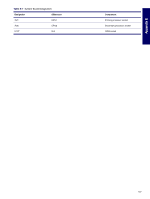
24-Pin Power (Main) 24-Pin Main Power Connector 13 24 1 +3.3 V 2 +3.3 V 3 GND 4 +5 V 5 GND 6 +5 V 7 GND 1 8 POK 9 +5 Vaux 10 +12 V-A 11 +12 V-A 12 +3.3 V 13 +3.3 V and +3.3V-Rsense 12 14 -12 V 15 GND 16 PS_ON_L 17 GND 18 GND 19 GND 20 21 +5 V 22 +5 V and +5 V-Rsense 23 +5 V 24 GND 6-Pin Power (Auxiliary System Board) CAUTION Be sure you can differentiate which power cable connects to the PCI Express x16 graphics card and which power cable connects to the system board. These two cables look very similar. The PCI Express power cable has a black connector and the power cable has a white connector. When power is present, you must NEVER connect the PCI Express power cable to the system board. If you do so, the system board may be damaged and your warranty voided. To see a picture of the PCI Express cable and where it must be connected, refer to the "PCI or PCI Express Installation" section on page 84. 6-Pin Power (Auxiliary System Board) Connector 46 13 Pin Color 1 ORG 2 ORG 3 YEL 4 BLK 5 BLK 6 YEL Signal +3.3V +3.3V +12V-A GND GND -12 V 162 CONNECTOR PINS
-
 1
1 -
2
-
3
-
4
-
5
-
6
-
7
-
8
-
9
-
10
-
11
-
12
-
13
-
14
-
15
-
16
-
17
-
18
-
19
-
20
-
21
-
22
-
23
-
24
-
25
-
26
-
27
-
28
-
29
-
30
-
31
-
32
-
33
-
34
-
35
-
36
-
37
-
38
-
39
-
40
-
41
-
42
-
43
-
44
-
45
-
46
-
47
-
48
-
49
-
50
-
51
-
52
-
53
-
54
-
55
-
56
-
57
-
58
-
59
-
60
-
61
-
62
-
63
-
64
-
65
-
66
-
67
-
68
-
69
-
70
-
71
-
72
-
73
-
74
-
75
-
76
-
77
-
78
-
79
-
80
-
81
-
82
-
83
-
84
-
85
-
86
-
87
-
88
-
89
-
90
-
91
-
92
-
93
-
94
-
95
-
96
-
97
-
98
-
99
-
100
-
101
-
102
-
103
-
104
-
105
-
106
-
107
-
108
-
109
-
110
-
111
-
112
-
113
-
114
-
115
-
116
-
117
-
118
-
119
-
120
-
121
-
122
-
123
-
124
-
125
-
126
-
127
-
128
-
129
-
130
-
131
-
132
-
133
-
134
-
135
-
136
-
137
-
138
-
139
-
140
-
141
-
142
-
143
-
144
-
145
-
146
-
147
-
148
-
149
-
150
-
151
-
152
-
153
-
154
-
155
-
156
-
 157
157 -
 158
158 -
 159
159 -
 160
160 -
 161
161 -
 162
162 -
 163
163 -
 164
164 -
 165
165 -
 166
166 -
 167
167 -
168
-
169
-
170
-
171
-
172
-
173
-
174
-
175
-
176
-
177
-
178
-
179
-
180
-
181
-
182
-
183
-
184
-
185
-
186
-
187
-
188
-
189
-
190
-
191
-
192
-
193
-
194
-
195
-
196
-
197
-
198
-
199
-
200
-
201
 |
 |
