HP dv8000 Maintenance and Service Guide - Page 128
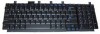
from the display, Remove the wireless antenna transceivers and cables
 |
UPC - 654954100226
View all HP dv8000 manuals
Add to My Manuals
Save this manual to your list of manuals |
Page 128 highlights
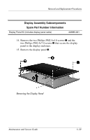
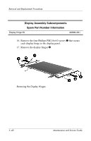
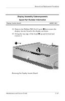
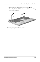
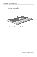
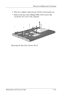
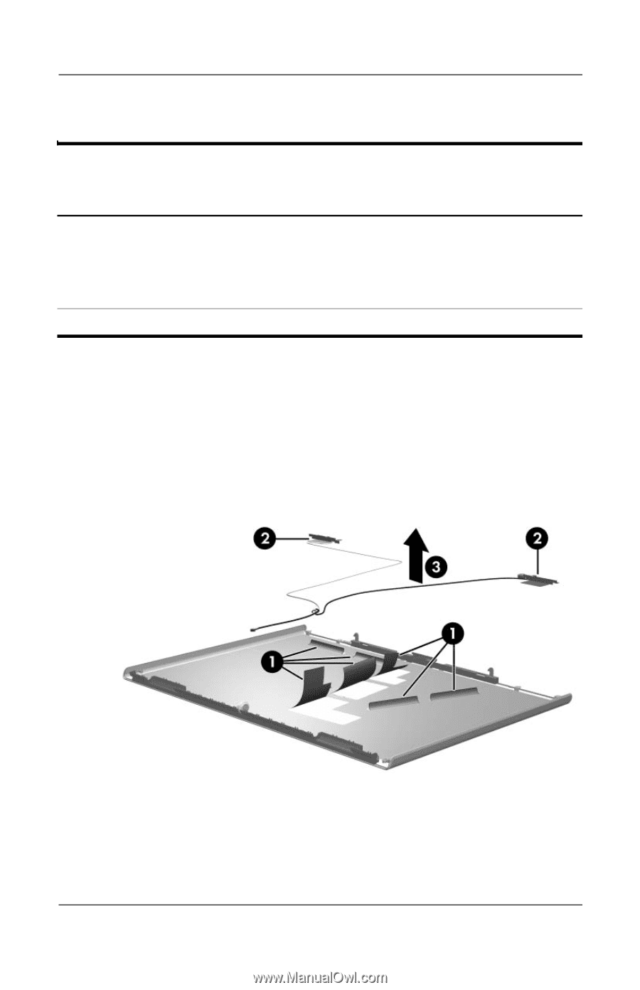
Removal and Replacement Procedures Display Assembly Subcomponents Spare Part Number Information Display Plastics Kit, includes: ■ Display enclosure ■ Display bezel ■ Display release latch actuator and hooks (not illustrated) Wireless Antenna Kit (includes cable and transceivers) 403881-001 403882-001 20. Release the retention tabs 1 built in to the display enclosure lining that secure the wireless antenna cables to the display enclosure. 21. Detach the wireless antenna transceivers 2 from the display enclosure. 22. Remove the wireless antenna transceivers and cables 1. Removing the Wireless Antenna Transceivers and Cables Reverse the above procedure to reassemble and install the display assembly. 5-42 Maintenance and Service Guide
-
 1
1 -
2
-
3
-
4
-
5
-
6
-
7
-
8
-
9
-
10
-
11
-
12
-
13
-
14
-
15
-
16
-
17
-
18
-
19
-
20
-
21
-
22
-
23
-
24
-
25
-
26
-
27
-
28
-
29
-
30
-
31
-
32
-
33
-
34
-
35
-
36
-
37
-
38
-
39
-
40
-
41
-
42
-
43
-
44
-
45
-
46
-
47
-
48
-
49
-
50
-
51
-
52
-
53
-
54
-
55
-
56
-
57
-
58
-
59
-
60
-
61
-
62
-
63
-
64
-
65
-
66
-
67
-
68
-
69
-
70
-
71
-
72
-
73
-
74
-
75
-
76
-
77
-
78
-
79
-
80
-
81
-
82
-
83
-
84
-
85
-
86
-
87
-
88
-
89
-
90
-
91
-
92
-
93
-
94
-
95
-
96
-
97
-
98
-
99
-
100
-
101
-
102
-
103
-
104
-
105
-
106
-
107
-
108
-
109
-
110
-
111
-
112
-
113
-
114
-
115
-
116
-
117
-
118
-
119
-
120
-
121
-
122
-
 123
123 -
 124
124 -
 125
125 -
 126
126 -
 127
127 -
 128
128 -
 129
129 -
 130
130 -
 131
131 -
 132
132 -
 133
133 -
134
-
135
-
136
-
137
-
138
-
139
-
140
-
141
-
142
-
143
-
144
-
145
-
146
-
147
-
148
-
149
-
150
-
151
-
152
-
153
-
154
-
155
-
156
-
157
-
158
-
159
-
160
-
161
-
162
-
163
-
164
-
165
-
166
-
167
-
168
-
169
-
170
-
171
-
172
-
173
-
174
-
175
-
176
-
177
-
178
-
179
-
180
-
181
-
182
-
183
-
184
-
185
-
186
-
187
-
188
-
189
-
190
-
191
-
192
-
193
-
194
-
195
-
196
-
197
-
198
-
199
-
200
-
201
-
202
-
203
-
204
-
205
-
206
-
207
-
208
-
209
-
210
-
211
-
212
-
213
-
214
-
215
-
216
-
217
-
218
-
219
-
220
-
221
-
222
-
223
-
224
-
225
-
226
-
227
-
228
-
229
-
230
-
231
-
232
-
233
-
234
-
235
-
236
-
237
-
238
-
239
-
240
-
241
-
242
-
243
-
244
-
245
-
246
 |
 |
5–42
Maintenance and Service Guide
Removal and Replacement Procedures
20. Release the retention tabs
1
built in to the display enclosure
lining that secure the wireless antenna cables to the display
enclosure.
21. Detach the wireless antenna transceivers
2
from the display
enclosure.
22. Remove the wireless antenna transceivers and cables
1
.
Removing the Wireless Antenna Transceivers and Cables
Reverse the above procedure to reassemble and install the
display assembly.
Display Assembly Subcomponents
Spare Part Number Information
Display Plastics Kit, includes:
■
Display enclosure
■
Display bezel
■
Display release latch actuator and hooks (not illustrated)
403881-001
Wireless Antenna Kit (includes cable and transceivers)
403882-001