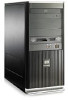
HP dx2290 Illustrated Parts & Service Map - HP Compaq dx2290 Business PC - Page 2
System Board, System Setup and Boot, POST Error/Warning Messages - specification
 |
View all HP dx2290 manuals
Add to My Manuals
Save this manual to your list of manuals |
Page 2 highlights
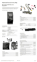
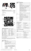
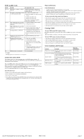
Miscellaneous Parts 1 Heatsink with alcohol pad and factory-applied thermal grease 448668-001 * Heatsink, Intel class K (for use in computers with Pentium D processors) 458806-001 2 Chassis fan 449207-001 * Mouse, PS/2, optical 417966-001 * Battery, real-time clock 153099-001 *Not shown System Board Computer Setup Menu (Continued) Heading Option / Description Advanced CPU type - view CPU speed - view Cache RAM - view Plug and Play OS - not used Primary video adapter - Allows you to select onboard, PCI-E, or PCI Onboard video memory size - allows you to select 1MB or 8MB PS/2 mouse - allows you to select disabled/enabled/auto detect Onboard PATA/SATA adapters - enable/disable USB Legacy Mode Support - enable.disable Onboard LAN - enable.disable Onboard LAN Boot ROM - enable.disable Supervisor Password - change or enable password User Password - change or enable password Change Supervisor Password - change password Onboard audio - set to auto/enable/disable Hardware monitor - view CPU temperature, CPU fan speed, and system fan speed Power After AC Power Failure - select system restart to stay off/power on/auto XD - enable/disable Boot Boot time diagnostic screen - enable/disable 1st thru 4th boot devices - set boot priority Floppy group boot priority - set priority within the group CD-ROM group boot priority - set priority within the group Hard drive group boot priority - set priority within the group Network group boot priority - set priority within the group Exit Exit saving changes Exit discarding changes Load setup defaults Discard changes Save changes System Board Connectors and Jumpers (position of some untitled components may vary in location) ATX1 Main Power F_USB2 Card Reader ATX12 CPU power in FDD Diskette drive AUX_IN Front audio in HD_ AUDIO Not used BT RTC Battery IDE1 IDE socket CLR_CMOS Clear CMOS PCI1 PCI socket #1 CLR_PSWD Clear Password PCI2 PCI socket # CPU_FAN Processor fan PCI_E PCI-E X1 socket DIMM1 Memory socket 1 PCIEX16 PCI-EX16 socket DIMM2 Memory socket 2 SATA1 First SATA socket F_AUDIO1 Front audio SATA2 Second SATA socket F_PANEL Front panel connector SYS_FAN Chassis fan F_USB1 Front I/O USB connector System Setup and Boot Basic system information regarding system information, setup, power management, hardware, and passwords is maintained in the Setup Utility held in the system ROM. The Setup Utility is accessed by pressing the F10 key when prompted (on screen) to do so during the boot sequence. If the screen prompt opportunity is missed, a restart will be necessary. System Hardware Interrupts IRQ System Function 0 Timer Interrupt 1 Keyboard 2 Interrupt Controller Cascade 3 Serial Port (COM B) 4 Serial Port (COM A) 5 Unused, available for PCI 6 Diskette Drive 7 Parallel Port (LPT 1) IRQ System Function 8 Real-Time Clock 9 Unused 10 Unused, available for PCI 11 Unused, available for PCI 12 Mouse 13 Coprocessor 14 Primary ATA (IDE) Controller 15 Secondary ATA (IDE) Controller POST Error/Warning Messages Once the display is available, the BIOS will classify all errors detected during POST into three categories: Category Action Single critical error requiring shutdown • Screen is cleared • Corresponding error message posted • Pause to allow message to be read • Turn computer off Single serious errors requiring user response • Corresponding error message posted • Pause to allow user input • Continue per user selection Single alert/warning requiring user attention • Corresponding error message posted • Pause to allow user input • Continue per user selection Multiple errors including one critical error • Resolve first critical error • Turn computer off Multiple errors including serious ones as • Resolve serious errors defined above • Proceed to alerts and warnings Computer Setup Menu Heading Option/Description Main System time - Allows you to set system time. System date - Allows you to set system date. Language - Allows you to select language. Floppy Diskette A - Allows you to set A drive to: disabled, 720 KB, 1.44 MB, 2.88 MB, or not installed. Drives 1 to 4: • Allows you to set: type, mode, and enable/disable SMART capability • Allows you to view: Device, vendor, size, LBA mode, Block mode, PIO mode, Async DMA, Ultra DMA, SATA SPEED, and NCQ. System Information - Lists the following main system specifications: • Installed memory • Memory Bank 1 • Memory Bank 2 • BIOS revision • Core version • Model number • Product number • Build ID dx2290 Illustrated Parts & Service Map, MT Chassis 448511-002 page 2
-
 1
1 -
 2
2 -
 3
3
 |
 |
