HP dx2420 Hardware Reference Guide - dx2420 Microtower Model
HP dx2420 - Microtower PC Manual
 |
View all HP dx2420 manuals
Add to My Manuals
Save this manual to your list of manuals |
HP dx2420 manual content summary:
- HP dx2420 | Hardware Reference Guide - dx2420 Microtower Model - Page 1
Hardware Reference Guide - dx2420 Microtower Model HP Compaq Business PC - HP dx2420 | Hardware Reference Guide - dx2420 Microtower Model - Page 2
herein is subject to change without notice. Microsoft, Windows, and Windows Vista are either trademarks or registered trademarks of Microsoft consent of Hewlett-Packard Company. Hardware Reference Guide HP Compaq Business PC dx2420 Microtower Model First Edition (January 2009) Document Part Number: - HP dx2420 | Hardware Reference Guide - dx2420 Microtower Model - Page 3
About This Book This guide provides basic information for upgrading this computer model. WARNING! Text set off in this manner indicates that failure to follow directions could result in bodily harm or loss of life. - HP dx2420 | Hardware Reference Guide - dx2420 Microtower Model - Page 4
iv About This Book ENWW - HP dx2420 | Hardware Reference Guide - dx2420 Microtower Model - Page 5
the Windows Logo Key 6 Serial Number Location ...7 2 Hardware Upgrades Warnings and Cautions ...8 Removing the Computer Access Panel 9 Replacing the Computer Access Panel 10 Removing the Front Bezel ...11 Removing Bezel Blanks ...12 Replacing the Front Bezel ...13 Installing Additional Memory - HP dx2420 | Hardware Reference Guide - dx2420 Microtower Model - Page 6
Appendix B Battery Replacement Appendix C External Security Devices Installing a Security Lock ...45 Cable Lock ...45 Padlock ...46 HP Business PC Security Lock 46 Appendix D Electrostatic Discharge Preventing Electrostatic Damage ...49 Grounding Methods ...49 Appendix E Computer Operating - HP dx2420 | Hardware Reference Guide - dx2420 Microtower Model - Page 7
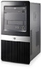
The HP Compaq Microtower features may vary depending on the model. For a complete listing of the hardware and software installed in the computer, run the diagnostic utility (included on some computer models only). Instructions for using the utility are provided in the Troubleshooting Guide. Figure - HP dx2420 | Hardware Reference Guide - dx2420 Microtower Model - Page 8
Activity Light 2 Optical Drive Activity Lights 7 Optical Drive Eject Buttons 3 3.5-inch Media Card Reader (optional)2 8 Headphone Connector 4 Microphone Connector 9 USB (Universal Serial Bus) 2.0 Ports 5 Dual-State Power Button 1 Some models have bezel blanks covering one or both of - HP dx2420 | Hardware Reference Guide - dx2420 Microtower Model - Page 9
DUO ● Memory Stick (MS) ● Memory Stick Select ● Memory Stick PRO ● MagicGate Memory Stick (MG) ● Memory Stick Duo (MS Duo) Duo (MS PRO Duo) ● Memory Stick PRO- ● MagicGate Memory ● Memory Stick PRO HG Duo Duo (MS PRO) ● Memory Stick Micro (M2) (adapter required) ENWW Media Card Reader - HP dx2420 | Hardware Reference Guide - dx2420 Microtower Model - Page 10
-45 Network Connector 9 VGA Monitor Connector (blue) 5 PS/2 Mouse Connector (green) 10 PS/2 Keyboard Connector (purple) NOTE: Arrangement and number of connectors may vary by model. The monitor connector on the system board is inactive when a PCI Express x16 graphics card is installed in the - HP dx2420 | Hardware Reference Guide - dx2420 Microtower Model - Page 11
) to open pop-up menus in a Microsoft Office application. May perform other functions in other software applications. 8 Windows Logo Keys1 Used to open the Start menu in Microsoft Windows. Used in combination with other keys to perform other functions. 9 Alt Keys Used in combination with another - HP dx2420 | Hardware Reference Guide - dx2420 Microtower Model - Page 12
to identify the Windows Logo key. Table 1-5 Windows Logo Key Functions The following Windows Logo Key functions are available in Microsoft Windows XP and Microsoft Windows Vista. Windows Logo Key Displays or hides the Start menu Windows Logo Key + d Displays the Desktop Windows Logo Key - HP dx2420 | Hardware Reference Guide - dx2420 Microtower Model - Page 13
serial number and product ID number that are located on the top cover of the computer. Keep these numbers available for use when contacting customer service for assistance. Figure 1-6 Serial Number and Product ID Location ENWW Serial Number Location 7 - HP dx2420 | Hardware Reference Guide - dx2420 Microtower Model - Page 14
Before performing upgrades be sure to carefully read all of the applicable instructions, cautions, and warnings in this guide. WARNING! To reduce the risk of personal injury from electrical shock, hot surfaces, or fire: Disconnect the power cord from the wall outlet and allow the internal system - HP dx2420 | Hardware Reference Guide - dx2420 Microtower Model - Page 15
the access panel back (2) about 1.3 cm (1/2 inch), then lift it off the unit. NOTE: You may want to lay the computer on its side to install internal parts. Be sure the side with the access panel is facing up. Figure 2-1 Removing the Computer Access Panel ENWW Removing the Computer Access Panel 9 - HP dx2420 | Hardware Reference Guide - dx2420 Microtower Model - Page 16
Replacing the Computer Access Panel Place the access panel on the chassis with about 1.3 cm (1/2 inch) of the panel that the hole for the screw is aligned with the hole in the chassis and tighten the screw (2). Figure 2-2 Replacing the Computer Access Panel 10 Chapter 2 Hardware Upgrades ENWW - HP dx2420 | Hardware Reference Guide - dx2420 Microtower Model - Page 17
system board as long as the system is plugged into an active AC outlet. You must disconnect the power cord to avoid damage to the internal components of the computer. 5. Remove the computer access panel. 6. Press outward on the three latches on the right side of the bezel (1), then rotate the - HP dx2420 | Hardware Reference Guide - dx2420 Microtower Model - Page 18
before installing a HP. 3. To remove the 3.5-inch bezel blank, press the two retaining tabs towards the outer left edge of the bezel (2) and pull the bezel blank inwards to free it from the front bezel (3). Figure 2-4 Removing a Bezel Blank 4. Replace the front bezel. 12 Chapter 2 Hardware Upgrades - HP dx2420 | Hardware Reference Guide - dx2420 Microtower Model - Page 19
Replacing the Front Bezel Insert the three hooks on the left side of the bezel into the slots on the chassis (1) and rotate the bezel on from left to right (2) so that it snaps in place. Figure 2-5 Replacing the Front Bezel ENWW Replacing the Front Bezel 13 - HP dx2420 | Hardware Reference Guide - dx2420 Microtower Model - Page 20
● 512Mbit and 1Gbit non-ECC memory technologies ● single-sided and double-sided DIMMs ● DIMMs constructed with x8 and x16 DDR devices; DIMMs constructed with x4 SDRAM are not supported NOTE: The system will not operate properly if you install unsupported DIMMs. 14 Chapter 2 Hardware Upgrades ENWW - HP dx2420 | Hardware Reference Guide - dx2420 Microtower Model - Page 21
mode, or flex mode, depending on how the DIMMs are installed. ● The system will operate in single channel mode if the DIMM sockets are populated in one channel only. ● The system will operate in a higher-performing dual channel mode if the memory capacity of the DIMM in Channel A is equal to the - HP dx2420 | Hardware Reference Guide - dx2420 Microtower Model - Page 22
. When upgrading the memory, it is important to use memory modules with gold-plated metal contacts to prevent corrosion and/or oxidation resulting from having incompatible metals in contact with each other. Static electricity can damage the electronic components of the computer or optional cards - HP dx2420 | Hardware Reference Guide - dx2420 Microtower Model - Page 23
the way down into the socket and sit evenly in the socket to avoid memory corruption. Make sure the latches are in the closed position (3). 9. Repeat steps 7 and 8 to install any additional modules. 10. Replace the computer access panel. 11. Reconnect the power cord and any external devices, then - HP dx2420 | Hardware Reference Guide - dx2420 Microtower Model - Page 24
slot NOTE: You can install a PCI Express x1, x4, x8, or x16 expansion card in the PCI Express x16 expansion slot. To remove, replace, or add an expansion card: 1. Remove/disengage any the power cord to avoid damage to the internal components of the computer. 18 Chapter 2 Hardware Upgrades ENWW - HP dx2420 | Hardware Reference Guide - dx2420 Microtower Model - Page 25
On the rear of the computer, a slot cover lock secures the expansion card brackets in place. Remove the screw from the slot cover lock then slide Before installing an expansion card, remove the expansion slot cover or the existing expansion card. ENWW Removing or Installing an Expansion Card 19 - HP dx2420 | Hardware Reference Guide - dx2420 Microtower Model - Page 26
that covers the expansion slot. Be sure to remove the appropriate shield for the expansion card you are installing. Figure 2-10 Removing an Expansion Slot Cover b. If you are removing a standard PCI card, hold the card at each end and carefully rock it back and forth until the connectors pull free - HP dx2420 | Hardware Reference Guide - dx2420 Microtower Model - Page 27
packaging. 10. If you are not installing a new expansion card, install an expansion slot cover to close the open slot. CAUTION: After removing an expansion card, you must replace it with a new card or expansion slot cover for proper cooling of internal components during operation. ENWW Removing or - HP dx2420 | Hardware Reference Guide - dx2420 Microtower Model - Page 28
with the screw that was previously removed. Figure 2-14 Securing the Expansion Cards and Slot Covers 13. Connect external cables to the installed card, if needed. Connect internal cables to the system board, if needed. 14. Replace the computer access panel. 22 Chapter 2 Hardware Upgrades ENWW - HP dx2420 | Hardware Reference Guide - dx2420 Microtower Model - Page 29
for instructions on using Computer Setup. Drive Positions Figure 2-15 Drive Positions 1 Two 5.25-inch external drive bays for optional drives (optical drives shown) 2 One 3.5-inch external drive bay for optional drive (media card reader shown) 3 Primary 3.5-inch internal hard drive bay 4 Secondary - HP dx2420 | Hardware Reference Guide - dx2420 Microtower Model - Page 30
media card reader to the USB connector labeled JUSB2. ● The system does not support Parallel ATA (PATA) optical drives or PATA hard drives. ● You may install other drives use M3 metric screws. The HP-supplied M3 metric guide screws (1) are black. The HP-supplied 6-32 standard screws (2) are silver. - HP dx2420 | Hardware Reference Guide - dx2420 Microtower Model - Page 31
force when inserting a drive. Avoid exposing a hard drive to liquids, temperature extremes, or products that have magnetic fields such as monitors or speakers. If a drive must be mailed, place the drive in a bubble-pack mailer or other protective packaging and label the package "Fragile: Handle - HP dx2420 | Hardware Reference Guide - dx2420 Microtower Model - Page 32
. Figure 2-17 System Board Drive Connections Table 2-3 System Board Drive Connections No. System Board Connector System Board Label 1 Media Card Reader JUSB2 2 Diskette Drive FDD1 3 SATA1 SATA1 4 SATA3 SATA3 5 SATA2 SATA2 6 SATA4 SATA4 Color white black dark blue light - HP dx2420 | Hardware Reference Guide - dx2420 Microtower Model - Page 33
system board as long as the system is plugged into an active AC outlet. You must disconnect the power cord to avoid damage to the internal components of the computer. 5. Remove the access panel and front bezel. 6. Disconnect the power cable (1) and data cable (2) from the rear of the optical drive - HP dx2420 | Hardware Reference Guide - dx2420 Microtower Model - Page 34
7. Remove the two screws that secure the drive to the drive cage (1), then slide the drive out of the front of the chassis (2). Figure 2-19 Removing the Optical Drive 28 Chapter 2 Hardware Upgrades ENWW - HP dx2420 | Hardware Reference Guide - dx2420 Microtower Model - Page 35
is plugged into an active AC outlet. You must disconnect the power cord to avoid damage to the internal components of the computer. 5. Remove the access panel and front bezel. 6. If you are installing a drive in a bay covered by a bezel blank, remove the front bezel then remove the bezel blank. See - HP dx2420 | Hardware Reference Guide - dx2420 Microtower Model - Page 36
. Figure 2-21 Connecting the Power and Data Cables 12. Replace the front bezel and access panel. 13. Reconnect the power bay may contain a diskette drive or a media card reader. 1. Remove/disengage any security devices that internal components of the computer. 5. Remove the access panel and front - HP dx2420 | Hardware Reference Guide - dx2420 Microtower Model - Page 37
, disconnect the data cable (1) and power cable (2) from the back of the drive. Figure 2-22 Disconnecting the Diskette Drive Cables b. If you are removing a media card reader, disconnect the USB cable from the system board. Figure 2-23 Disconnecting the Media - HP dx2420 | Hardware Reference Guide - dx2420 Microtower Model - Page 38
24 Removing a 3.5-inch Device (Media Card Reader Shown) Installing a Drive into the 3.5-inch External Drive internal components of the computer. 5. Remove the access panel and front bezel. 6. If you are installing a diskette drive or media card screws installed on the sides of the drive, remove - HP dx2420 | Hardware Reference Guide - dx2420 Microtower Model - Page 39
FDD1. b. If installing a media card reader, connect the USB cable from the media card reader to the USB connector on the system board labeled JUSB2. NOTE: Refer to System Board Drive Connections on page 26 for an illustration of the system board drive connectors. 11. Replace - HP dx2420 | Hardware Reference Guide - dx2420 Microtower Model - Page 40
replacing the primary hard drive, make sure you have created a Recovery Disc Set to restore the operating system, software drivers , and any software applications that were preinstalled on the computer. If you do not have this CD set, select Start > HP damage to the internal components of the - HP dx2420 | Hardware Reference Guide - dx2420 Microtower Model - Page 41
. Figure 2-27 Releasing the Hard Drive Cage 8. Lift the hard disk drive cage out of the chassis. Figure 2-28 Removing the Hard Drive Cage ENWW Installing Additional Drives 35 - HP dx2420 | Hardware Reference Guide - dx2420 Microtower Model - Page 42
disk drive cage (1), then slide the hard disk drive out of the hard disk drive cage (2). Figure 2-30 Removing the Hard Drive 36 Chapter 2 Hardware Upgrades ENWW - HP dx2420 | Hardware Reference Guide - dx2420 Microtower Model - Page 43
drive cables are facing the top of the drive cage. NOTE: If you are replacing an old drive with a new drive, use the four retainer screws from the old drive to install the new drive. NOTE: If you are installing a second hard drive, use four of the extra standard 6-32 screws that are - HP dx2420 | Hardware Reference Guide - dx2420 Microtower Model - Page 44
Connecting the Hard Drive Cables CAUTION: Never crease or bend a SATA data cable tighter than a 30 mm (1.18 in) radius. A sharp bend can break the internal wires. 4. Place the hard disk drive cage into the chassis (1), then slide it down toward the bottom of the chassis until it locks into place - HP dx2420 | Hardware Reference Guide - dx2420 Microtower Model - Page 45
labeled SATA1 to avoid any hard drive performance problems. If you are adding a second hard drive replacing the primary hard drive, use the Recovery Disc Set to restore the operating system, software drivers, and any software applications that were preinstalled on the computer. ENWW Installing - HP dx2420 | Hardware Reference Guide - dx2420 Microtower Model - Page 46
A Specifications Table A-1 Specifications Desktop Dimensions Height 14.76 in 37.5 cm Width 6.98 in of change is 10° C/Hr. The upper limit may be limited by the type and number of options installed. Heat Dissipation Maximum 1575 BTU/hr 397 kg-cal/hr Typical (idle) 307 BTU/hr 77 kg-cal - HP dx2420 | Hardware Reference Guide - dx2420 Microtower Model - Page 47
Table A-1 Specifications (continued) Rated Input Current (maximum)1 8A @ 100 VAC 4A @ 200 VAC 1 This system utilizes a passive power factor corrected power supply. The power factor correction is - HP dx2420 | Hardware Reference Guide - dx2420 Microtower Model - Page 48
provides power to the real-time clock. When replacing the battery, use a battery equivalent to the battery originally installed in the computer. The computer comes with a 3-volt lithium coin cell battery. WARNING! The computer contains an internal lithium manganese dioxide battery. There is a risk - HP dx2420 | Hardware Reference Guide - dx2420 Microtower Model - Page 49
NOTE: On some computer models, it may be necessary to remove an internal component to gain access to the battery. 7. Depending on the type of battery holder on the system board, complete the following instructions to replace the battery. Type 1 a. Lift the battery out of its holder. Figure B-1 - HP dx2420 | Hardware Reference Guide - dx2420 Microtower Model - Page 50
to complete this procedure. 8. Replace the computer access panel. 9. Plug in the computer and turn on power to the computer. 10. Reset the date and time, your passwords, and any special system setups using Computer Setup. Refer to the Computer Setup (F10) Utility Guide. 11. Lock any security devices - HP dx2420 | Hardware Reference Guide - dx2420 Microtower Model - Page 51
C External Security Devices NOTE: For information on data security features, refer to the Computer Setup (F10) Utility Guide and the Desktop Management Guide. Installing a Security Lock The security locks displayed below and on the following pages can be used to secure the computer. Cable Lock - HP dx2420 | Hardware Reference Guide - dx2420 Microtower Model - Page 52
Padlock Figure C-2 Installing a Padlock HP Business PC Security Lock 1. Fasten the security cable by looping it around a stationary object. Figure C-3 Securing the Cable to a Fixed Object 46 Appendix C External Security Devices ENWW - HP dx2420 | Hardware Reference Guide - dx2420 Microtower Model - Page 53
2. Thread the keyboard and mouse cables through the lock. Figure C-4 Threading the Keyboard and Mouse Cables 3. Screw the lock to the chassis using the screw provided. Figure C-5 Attaching the Lock to the Chassis ENWW Installing a Security Lock 47 - HP dx2420 | Hardware Reference Guide - dx2420 Microtower Model - Page 54
4. Insert the plug end of the security cable into the lock (1) and push the button in (2) to engage the lock. Use the key provided to disengage the lock. Figure C-6 Engaging the Lock 48 Appendix C External Security Devices ENWW - HP dx2420 | Hardware Reference Guide - dx2420 Microtower Model - Page 55
. Use one or more of the following methods when handling or installing electrostatic-sensitive parts: ● Use a wrist strap connected by a HP authorized dealer, reseller, or service provider. NOTE: For more information on static electricity, contact an HP authorized dealer, reseller, or service - HP dx2420 | Hardware Reference Guide - dx2420 Microtower Model - Page 56
of the desktop unit as this also restricts airflow. ● Never operate the computer with the access panel or any of the expansion card slot covers the ventilation slots on the monitor with any type of material. ● Install or enable power management functions of the operating system or other software - HP dx2420 | Hardware Reference Guide - dx2420 Microtower Model - Page 57
the finish. Safety If any object or liquid falls into the drive, immediately unplug the computer and have it checked by an authorized HP service provider. Shipping Preparation Follow these suggestions when preparing to ship the computer: 1. Back up the hard drive files on PD discs, tape cartridges - HP dx2420 | Hardware Reference Guide - dx2420 Microtower Model - Page 58
cable lock 45 HP Business PC Security Lock 46 padlock 46 F front bezel removing 11 M media card reader features 3 52 Index installing 32 removing 30 memory installing 14 populating sockets 15 specifications 14 microphone connector 2, 4 monitor, connecting 4 mouse connector 4 N network connector - HP dx2420 | Hardware Reference Guide - dx2420 Microtower Model - Page 59
20 PCI Express card 21 S security cable lock 45 HP Business PC Security Lock 46 padlock 46 serial number location 7 shipping preparation 51 specifications computer 40 memory 14 system board drive connections 26 U unlocking access panel 45 USB ports front panel 2 rear panel 4 V ventilation guidelines
-
 1
1 -
 2
2 -
 3
3 -
 4
4 -
 5
5 -
 6
6 -
 7
7 -
8
-
9
-
10
-
11
-
12
-
13
-
14
-
15
-
16
-
17
-
18
-
19
-
20
-
21
-
22
-
23
-
24
-
25
-
26
-
27
-
28
-
29
-
30
-
31
-
32
-
33
-
34
-
35
-
36
-
37
-
38
-
39
-
40
-
41
-
42
-
43
-
44
-
45
-
46
-
47
-
48
-
49
-
50
-
51
-
52
-
53
-
54
-
55
-
56
-
57
-
58
-
59
 |
 |

Hardware Reference Guide - dx2420
Microtower Model
HP Compaq Business PC