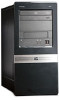
HP dx7510 Service Reference Guide: HP Compaq dx7510/dx7518 Business PC
HP dx7510 - Microtower PC Manual
 |
View all HP dx7510 manuals
Add to My Manuals
Save this manual to your list of manuals |
HP dx7510 manual content summary:
- HP dx7510 | Service Reference Guide: HP Compaq dx7510/dx7518 Business PC - Page 1
Service Reference Guide HP Compaq dx7510/dx7518 Business PC - HP dx7510 | Service Reference Guide: HP Compaq dx7510/dx7518 Business PC - Page 2
HP products and services are set forth in the express warranty statements accompanying such products and services. Nothing herein should be construed as constituting an additional warranty. HP of Hewlett-Packard Company. Service Reference Guide Business PCs First Edition (April 2009) Document Part - HP dx7510 | Service Reference Guide: HP Compaq dx7510/dx7518 Business PC - Page 3
About This Book WARNING! Text set off in this manner indicates that failure to follow directions could result in bodily harm or loss of life. CAUTION: Text set off in this manner indicates that failure to follow directions could result in damage to equipment or loss of information. NOTE: Text set - HP dx7510 | Service Reference Guide: HP Compaq dx7510/dx7518 Business PC - Page 4
iv About This Book - HP dx7510 | Service Reference Guide: HP Compaq dx7510/dx7518 Business PC - Page 5
Installing the Operating System ...1 Installing or Upgrading Device Drivers 1 HP Backup and Recovery Manager ...1 2 Computer Setup ( Printing Information in HP Insight Diagnostics 18 Downloading the Latest Version of HP Insight Diagnostics 19 Protecting the Software ...19 HP Backup and Recovery - HP dx7510 | Service Reference Guide: HP Compaq dx7510/dx7518 Business PC - Page 6
Keyboard ...28 Cleaning the Monitor ...28 Cleaning the Mouse ...29 Service Considerations ...29 Power Supply Fan ...29 Tools and Software Requirements Coin Cell Battery 30 6 Removal and Replacement Procedures Microtower (MT) Chassis Serial Number Location ...31 Preparation for Disassembly ...32 - HP dx7510 | Service Reference Guide: HP Compaq dx7510/dx7518 Business PC - Page 7
Type 1 Battery Holder ...69 Type 2 Battery Holder ...70 Type 3 Battery Holder ...71 Installing a Security Lock ...72 Cable Lock ...72 Padlock ...72 HP Business PC Security Lock 73 Hood Sensor ...75 Port Cover ...75 Appendix A Connector Pin Assignments Keyboard ...76 Mouse ...76 Parallel Interface - HP dx7510 | Service Reference Guide: HP Compaq dx7510/dx7518 Business PC - Page 8
Power Cord Requirements 83 Country-Specific Requirements ...84 Appendix C Troubleshooting Safety and Comfort ...85 Before You Call for Technical Support 85 Helpful Hints ...86 Solving General Problems ...88 Solving Hardware Installation Problems 91 Interpreting POST Diagnostic Front Panel - HP dx7510 | Service Reference Guide: HP Compaq dx7510/dx7518 Business PC - Page 9
instructions drivers for each of the devices. If prompted for the i386 directory, replace the path specification drivers. Obtain the latest support software, including support software for the operating system from http://www.hp.com/support. Select your country and language, select Download drivers - HP dx7510 | Service Reference Guide: HP Compaq dx7510/dx7518 Business PC - Page 10
Backup and Recovery Manager, refer to the HP Backup and Recovery Manager User Guide by selecting Start > HP Backup and Recovery > HP Backup and Recovery Manager Manual. NOTE: You can order a Recovery Disc Set from HP by calling the HP support center. Go to the following Web site, select your region - HP dx7510 | Service Reference Guide: HP Compaq dx7510/dx7518 Business PC - Page 11
cannot be used until they are unsecured. ● Enable or disable removable media boot ability. ● Enable or disable legacy diskette write ability (when supported by hardware). Using Computer Setup (F10) Utilities Computer Setup can be accessed only by turning the computer on or restarting the system. To - HP dx7510 | Service Reference Guide: HP Compaq dx7510/dx7518 Business PC - Page 12
Utility screen: ● System Information ● Standard CMOS Features ● Advanced BIOS Features ● Advanced Chipset Features ● Integrated Peripherals ● Power Management Standard CMOS Features on page 6 Advanced BIOS Features Table 2-4 Computer Setup-Advanced BIOS Features on page 7 Advanced Chipset Features - HP dx7510 | Service Reference Guide: HP Compaq dx7510/dx7518 Business PC - Page 13
Setup on page 11 (Action Choices) Table 2-10 Computer Setup-(Action Choices) on page 12 Computer Setup-System Information NOTE: Support for specific Computer Setup options may vary depending on the hardware configuration. Table 2-2 Computer Setup-System Information Option Description System - HP dx7510 | Service Reference Guide: HP Compaq dx7510/dx7518 Business PC - Page 14
Setup-Standard CMOS Features NOTE: Support for specific Computer Setup options may vary depending detect HDD size and head on selected channel ● set extended drive on selected channel to: ◦ None ◦ Auto ◦ Manual ● set access mode on selected channel to: ◦ CHS ◦ LBA ◦ Large ◦ Auto ● view: ◦ Capacity - HP dx7510 | Service Reference Guide: HP Compaq dx7510/dx7518 Business PC - Page 15
BIOS Features NOTE: Support for specific BIOS Features Option Description F11 Prompt Setting this feature to displayed will display the text F11 = Recovery during POST. Hiding this feature prevents the text from being displayed. However, pressing F11 will still attempt to boot to the HP - HP dx7510 | Service Reference Guide: HP Compaq dx7510/dx7518 Business PC - Page 16
Table 2-4 Computer Setup-Advanced BIOS Features (continued) First Boot Device Second Boot Device Third Boot Device hard drive S.M.A.R.T. capability. Computer Setup-Advanced Chipset Features NOTE: Support for specific Computer Setup options may vary depending on the hardware configuration. Table - HP dx7510 | Service Reference Guide: HP Compaq dx7510/dx7518 Business PC - Page 17
Peripherals NOTE: Support for specific Computer Setup Support Disables/enables USB legacy support. HD Audio Disables/enables HD audio controller. Onboard LAN Controller Disables/enables onboard LAN controller. Onboard LAN Boot ROM Disables/enables the boot ROM of the onboard LAN chip. HP - HP dx7510 | Service Reference Guide: HP Compaq dx7510/dx7518 Business PC - Page 18
or ECP+EPP, allows you to set the DMA channel for ECP Mode to 1 or 3. Computer Setup-Power Management Setup NOTE: Support for specific Computer Setup options may vary depending on the hardware configuration. Table 2-7 Computer Setup-Power Management Setup Option Description PCI-E Wake on PME - HP dx7510 | Service Reference Guide: HP Compaq dx7510/dx7518 Business PC - Page 19
are controlled automatically or manually: ● Auto (ESCD-Extended Storage Configuration Data) ● Manual BIOS can automatically configure all the 15 assigned to Computer Setup-Hardware Monitor Setup NOTE: Support for specific Computer Setup options may vary depending on the hardware configuration - HP dx7510 | Service Reference Guide: HP Compaq dx7510/dx7518 Business PC - Page 20
Computer Setup-(Action Choices) NOTE: Support for specific Computer Setup options may vary depending on the hardware configuration. Table 2-10 Computer Setup-(Action Choices) Option Description Load Optimized Defaults Allows you to reset - HP dx7510 | Service Reference Guide: HP Compaq dx7510/dx7518 Business PC - Page 21
can be found at http://www.hp.com under the Software & Driver Downloads for your specific model. Download the firmware files into a folder on the removable storage to the computer. 2. Boot to DOS. 3. Type N:\folder\BIOS.exe SAVE:ABC001.DAT (where N is the drive letter of the removable storage) - HP dx7510 | Service Reference Guide: HP Compaq dx7510/dx7518 Business PC - Page 22
to the Customer Support Center. NOTE: Third party devices may not be detected by HP Insight Diagnostics. Accessing HP Insight Diagnostics You must to the hard drive. Refer to the Computer Setup (F10) Utility Guide on the Documentation and Diagnostics DVD for more information. You can also change - HP dx7510 | Service Reference Guide: HP Compaq dx7510/dx7518 Business PC - Page 23
your specific keyboard. 5. In the End User License Agreement page, click Agree if you agree with the terms. The HP information about the computer. Architecture-Provides system BIOS and PCI device information. Asset Control-Shows supports SCSI, serial Advanced Technology HP Insight Diagnostics 15 - HP dx7510 | Service Reference Guide: HP Compaq dx7510/dx7518 Business PC - Page 24
the MSA controller. HP has found through experience that looking at operational history is one of the best ways to diagnose disk drive problems. Systems Insight a system. The Custom Test mode allows you to specifically select which devices, tests, and test parameters are run. 16 - HP dx7510 | Service Reference Guide: HP Compaq dx7510/dx7518 Business PC - Page 25
overall test progress of all devices being tested ● The test progress for each device being tested ● The elapsed test times for each device being tested HP Insight Diagnostics 17 - HP dx7510 | Service Reference Guide: HP Compaq dx7510/dx7518 Business PC - Page 26
Repair action that should help solve the problem. To find an error code description quickly Information in HP Insight Diagnostics You can save the information displayed in the HP Insight be 64MB or higher). USB 1.0 flash drives are not supported. 2. Click Save in the bottom right corner of the - HP dx7510 | Service Reference Guide: HP Compaq dx7510/dx7518 Business PC - Page 27
from the optical drive. Downloading the Latest Version of HP Insight Diagnostics 1. Go to http://www.hp.com. 2. Click the Software & Driver Downloads link. 3. Enter your product number (for example, dx2810) in the text box and press the Enter key. 4. Select your specific computer model. 5. Select - HP dx7510 | Service Reference Guide: HP Compaq dx7510/dx7518 Business PC - Page 28
Backup and Recovery Manager, refer to the HP Backup and Recovery Manager User Guide by selecting Start > HP Backup and Recovery > HP Backup and Recovery Manager Manual. NOTE: You can order a Recovery Disc Set from HP by calling the HP support center. Go to the following Web site, select your region - HP dx7510 | Service Reference Guide: HP Compaq dx7510/dx7518 Business PC - Page 29
4 Serial ATA (SATA) Drive Guidelines and Features NOTE: HP only supports the use of SATA hard drives on these models of computer. No Parallel ATA (PATA) drives are supported. SATA Hard Drives Serial ATA Hard Drive Characteristics Number of pins/conductors in data cable Number of pins in power - HP dx7510 | Service Reference Guide: HP Compaq dx7510/dx7518 Business PC - Page 30
and Recording Technology (SMART) ATA drives for the HP Personal Computers have built-in drive failure prediction that warns may differ from that marked on the hard drive or listed in the computer specification. Drive size calculations by drive manufacturers are bytes to the base 10 while - HP dx7510 | Service Reference Guide: HP Compaq dx7510/dx7518 Business PC - Page 31
to the procedures and precautions described in this chapter is essential for proper service. CAUTION: When the computer is plugged into an AC power source, voltage subsection illustrates the dx7500 chassis design. Microtower (MT) Figure 5-1 HP Compaq dx7510 Microtower Chassis Designations 23 - HP dx7510 | Service Reference Guide: HP Compaq dx7510/dx7518 Business PC - Page 32
Figure 5-2 HP Compaq dx7518 Microtower NOTE: The appearance of the front bezel may vary. Electrostatic Discharge Information A sudden discharge of static electricity from your finger or other conductor can - HP dx7510 | Service Reference Guide: HP Compaq dx7510/dx7518 Business PC - Page 33
Removing DIPs* from vinyl tray 2,000 V Removing DIPs* from Styrofoam 3,500 V Removing bubble pack from PCB 7,000 V Packing PCBs in foam-lined box 5,000 V *These are then multi-packaged inside plastic tubes, trays, or Styrofoam. 4,000 V 5,000 V 20,000 V 11,000 V 11,500 V 14,500 V 26,500 V - HP dx7510 | Service Reference Guide: HP Compaq dx7510/dx7518 Business PC - Page 34
such as ordinary plastic assembly aids and Styrofoam. ● Use field service tools, such as cutters, screwdrivers, and vacuums, that are Static-dissipative table or floor mats with hard tie to ground ● Field service kits ● Static awareness labels ● Wrist straps and footwear straps providing one-megohm - HP dx7510 | Service Reference Guide: HP Compaq dx7510/dx7518 Business PC - Page 35
Operating Guidelines To prevent overheating and to help prolong the life of the computer: ● Keep the computer away from excessive moisture, direct sunlight, and extremes of heat and cold. ● Operate the computer on a sturdy, level surface. Leave a 10.2-cm (4-inch) clearance on all vented sides of the - HP dx7510 | Service Reference Guide: HP Compaq dx7510/dx7518 Business PC - Page 36
To clean the computer case, follow the procedures described below: ● To remove light stains or dirt, use plain water with a clean, lint-free cloth or swab. ● For stronger stains, use a mild dishwashing liquid diluted with water. Rinse well by wiping it with a cloth or swab dampened with clear water. - HP dx7510 | Service Reference Guide: HP Compaq dx7510/dx7518 Business PC - Page 37
source before opening the computer to prevent system board or component damage. Tools and Software Requirements To service the computer, you need the following: ● Torx T-15 screwdriver (HP screwdriver with bits, PN 161946-001) ● Torx T-15 screwdriver with small diameter shank (for certain front - HP dx7510 | Service Reference Guide: HP Compaq dx7510/dx7518 Business PC - Page 38
parts being removed or replaced. CAUTION: When servicing this computer, ensure that cables are placed in the chassis you are working on in this guide for instructions on the replacement procedures. WARNING! This computer or return them to HP, their authorized partners, or their agents. - HP dx7510 | Service Reference Guide: HP Compaq dx7510/dx7518 Business PC - Page 39
described in this chapter is essential for proper service. After completing all necessary removal and replacement procedures, run the Diagnostics utility to verify that all components operate properly. NOTE: Not all features listed in this guide are available on all computers. Serial Number Location - HP dx7510 | Service Reference Guide: HP Compaq dx7510/dx7518 Business PC - Page 40
computer is in the "Standby," or "Suspend" modes. The power cord should always be disconnected before servicing a unit. 5. Disconnect the power cord from the electrical outlet and then from the computer. 6. damage the unit. 32 Chapter 6 Removal and Replacement Procedures Microtower (MT) Chassis - HP dx7510 | Service Reference Guide: HP Compaq dx7510/dx7518 Business PC - Page 41
Access Panel 1. Prepare the computer for disassembly (Preparation for Disassembly on page 32). 2. Loosen the captive thumbscrew (1) that secures the access panel to the computer chassis. 3. Slide the access panel back (2) about 1.3 cm (1/2 inch), then lift it off the unit. NOTE: You may want to lay - HP dx7510 | Service Reference Guide: HP Compaq dx7510/dx7518 Business PC - Page 42
then rotate the right side of the bezel off the chassis (2) followed by the left side. Figure 6-3 Removing the Front Bezel NOTE: Model dx7518 shown. NOTE: The appearance of the front bezel may vary. To reinstall the front bezel, reverse the removal procedure. 34 Chapter 6 Removal and Replacement - HP dx7510 | Service Reference Guide: HP Compaq dx7510/dx7518 Business PC - Page 43
removed before installing a drive. To remove a bezel blank: 1. Follow the instructions described in Front Bezel on page 34. 2. To remove the lower 5.25 be replaced at a later date, you can order a replacement blank from HP. 3. To remove the 3.5-inch bezel blank, press the two retaining tabs towards - HP dx7510 | Service Reference Guide: HP Compaq dx7510/dx7518 Business PC - Page 44
. To achieve the maximum memory support, you can populate the system DIMMs The DDR3-SDRAM DIMMs must also: ● support CAS latency 7 DDR3 1066 Mhz (7-7-7 timing) JEDEC SPD information In addition, the computer supports: ● 512Mbit, 1Gbit, and 2Gbit with x4 SDRAM are not supported NOTE: The system will - HP dx7510 | Service Reference Guide: HP Compaq dx7510/dx7518 Business PC - Page 45
Populating DIMM Sockets There are four DIMM sockets on the system board, with two sockets per channel. The sockets are labeled XMM1, XMM2, XMM3, and XMM4. Sockets XMM1 and XMM2 operate in memory channel A. Sockets XMM3 and XMM4 operate in memory channel B. Figure 6-5 DIMM Socket Locations Table 6-1 - HP dx7510 | Service Reference Guide: HP Compaq dx7510/dx7518 Business PC - Page 46
! To reduce risk of personal injury from hot surfaces, allow the internal system components to cool before touching. 38 Chapter 6 Removal and Replacement Procedures Microtower (MT) Chassis - HP dx7510 | Service Reference Guide: HP Compaq dx7510/dx7518 Business PC - Page 47
4. Open both latches of the memory module socket (1), and insert the memory module into the socket (2). Figure 6-6 Installing a DIMM NOTE: A memory module can be installed in only one way. Match the notch on the module with the tab on the memory socket. A DIMM must occupy the XMM1 socket. Always - HP dx7510 | Service Reference Guide: HP Compaq dx7510/dx7518 Business PC - Page 48
expansion socket on the system board and the corresponding expansion slot on the back of the computer chassis. 40 Chapter 6 Removal and Replacement Procedures Microtower (MT) Chassis - HP dx7510 | Service Reference Guide: HP Compaq dx7510/dx7518 Business PC - Page 49
4. On the rear of the computer, a slot cover lock secures the expansion card brackets in place. Remove the screw from the slot cover lock then slide the slot cover lock up to remove it from the chassis. Figure 6-8 Opening the Slot Cover Lock 5. Before installing an expansion card, remove the - HP dx7510 | Service Reference Guide: HP Compaq dx7510/dx7518 Business PC - Page 50
. 7. If you are not installing a new expansion card, install an expansion slot cover to close the open slot. 42 Chapter 6 Removal and Replacement Procedures Microtower (MT) Chassis - HP dx7510 | Service Reference Guide: HP Compaq dx7510/dx7518 Business PC - Page 51
CAUTION: After removing an expansion card, you must replace it with a new card or expansion slot cover for proper cooling of internal components during operation. 8. To install a new expansion card, hold the card just above the expansion socket on the system board then move the card toward the rear - HP dx7510 | Service Reference Guide: HP Compaq dx7510/dx7518 Business PC - Page 52
Reconfigure the computer, if necessary. Refer to the Computer Setup (F10) Utility Guide for instructions on using Computer Setup. Cable Management Always follow good cable management practices when working failed power supply. 44 Chapter 6 Removal and Replacement Procedures Microtower (MT) Chassis - HP dx7510 | Service Reference Guide: HP Compaq dx7510/dx7518 Business PC - Page 53
Cable Connections System board connectors are color-coded to make it easier to find the proper connection. Connector Name ATXPOWER ATX_CPU FLOPPY CHASSIS_FAN1 CPU FAN F_PANEL F_USB1 F_AUDIO SPEAKER F_1394 F_USB2 SATA0 SATA1 SATA4 SATA5 Connector Color White White Black Brown White Black White - HP dx7510 | Service Reference Guide: HP Compaq dx7510/dx7518 Business PC - Page 54
Drives The computer supports up to five drives that may be installed in various configurations. This section describes the procedure for replacing or upgrading the storage drives. A Torx T-15 screwdriver is needed to remove and install the guide screws on a drive. Drive Positions Figure 6-14 Drive - HP dx7510 | Service Reference Guide: HP Compaq dx7510/dx7518 Business PC - Page 55
media card reader to the USB connector labeled F_USB3. ● The system does not support Parallel ATA (PATA) optical drives or PATA hard drives. ● You may drives use M3 metric screws. The HP-supplied 6-32 standard screws (1) are silver. The HP-supplied M3 metric guide screws (2) are black. Figure 6- - HP dx7510 | Service Reference Guide: HP Compaq dx7510/dx7518 Business PC - Page 56
4 SATA4 SATA4 5 Media Card Reader F_USB3 6 Diskette Drive FLOPPY Color dark blue white light blue orange black black 48 Chapter 6 Removal and Replacement Procedures Microtower (MT) Chassis - HP dx7510 | Service Reference Guide: HP Compaq dx7510/dx7518 Business PC - Page 57
Removing an Optical Drive CAUTION: All removable media should be taken out of a drive before removing the drive from the computer. To remove an optical drive: 1. Prepare the computer for disassembly (Preparation for Disassembly on page 32). 2. Remove the access panel (Access Panel on page 33). 3. - HP dx7510 | Service Reference Guide: HP Compaq dx7510/dx7518 Business PC - Page 58
are adding a second optical drive, connect the SATA data cable to the orange system board connector labeled SATA4. 50 Chapter 6 Removal and Replacement Procedures Microtower (MT) Chassis - HP dx7510 | Service Reference Guide: HP Compaq dx7510/dx7518 Business PC - Page 59
8. Connect the power cable (1) and data cable (2) to the rear of the optical drive. Figure 6-20 Connecting the Power and Data Cables 9. Replace the front bezel and access panel. 10. Reconnect the power cord and turn on the computer. 11. Lock any security devices that were disengaged when the access - HP dx7510 | Service Reference Guide: HP Compaq dx7510/dx7518 Business PC - Page 60
install an external 3.5-inch drive, refer to Installing a Drive into the 3.5-inch External Drive Bay on page 53. 52 Chapter 6 Removal and Replacement Procedures Microtower (MT) Chassis - HP dx7510 | Service Reference Guide: HP Compaq dx7510/dx7518 Business PC - Page 61
Installing a Drive into the 3.5-inch External Drive Bay The 3.5-inch external drive bay on the front of the computer can be configured with a media card reader or a diskette drive. 1. Prepare the computer for disassembly (Preparation for Disassembly on page 32). 2. Remove the access panel (Access - HP dx7510 | Service Reference Guide: HP Compaq dx7510/dx7518 Business PC - Page 62
Disc Set to restore the operating system, software drivers, and any software applications that were preinstalled on the computer. If you do not have this CD set, select Start > HP Backup and Recovery and create it now. 1. Prepare the computer for Microtower (MT) Chassis - HP dx7510 | Service Reference Guide: HP Compaq dx7510/dx7518 Business PC - Page 63
5. Push down the latch on the side of the hard drive cage (1), then slide the hard drive cage away from the bottom of the chassis (2) as shown below. Figure 6-25 Releasing the Hard Drive Cage 6. Lift the hard drive cage out of the chassis. Figure 6-26 Removing the Hard Drive Cage Drives 55 - HP dx7510 | Service Reference Guide: HP Compaq dx7510/dx7518 Business PC - Page 64
: To install an internal 3.5-inch hard drive, refer to Installing an Internal 3.5-inch Hard Drive on page 57. 56 Chapter 6 Removal and Replacement Procedures Microtower (MT) Chassis - HP dx7510 | Service Reference Guide: HP Compaq dx7510/dx7518 Business PC - Page 65
Installing an Internal 3.5-inch Hard Drive 1. Follow the steps in Removing an Internal 3.5-inch Hard Drive on page 54 to remove the hard drive cage and, if necessary, the existing hard drive. 2. Slide the new drive into the hard drive cage (1), aligning the drive with the four screw holes on the - HP dx7510 | Service Reference Guide: HP Compaq dx7510/dx7518 Business PC - Page 66
toward the bottom of the chassis until it locks into place (2). Figure 6-31 Installing the Hard Drive Cage 58 Chapter 6 Removal and Replacement Procedures Microtower (MT) Chassis - HP dx7510 | Service Reference Guide: HP Compaq dx7510/dx7518 Business PC - Page 67
drive data cable to the dark blue connector labeled SATA1 to avoid any hard drive performance problems. If you are adding a second hard drive, connect the data cable to the light the operating system, software drivers, and any software applications that were preinstalled on the computer. Drives 59 - HP dx7510 | Service Reference Guide: HP Compaq dx7510/dx7518 Business PC - Page 68
the screw (1) that secures the housing to the chassis, slide the housing up (2), and then pull the assembly away from the chassis while guiding the cables through the hole in the chassis. To install the housing assembly, reverse the removal procedures. 60 Chapter 6 Removal and Replacement Procedures - HP dx7510 | Service Reference Guide: HP Compaq dx7510/dx7518 Business PC - Page 69
(1) to disengage it from the chassis, rotate the switch to the left (2), and then pull it to the right and away from the chassis while guiding the wires through the hole in the chassis. To install the power switch/LED assembly, reverse the removal procedures. Power Switch/LED Assembly 61 - HP dx7510 | Service Reference Guide: HP Compaq dx7510/dx7518 Business PC - Page 70
back through the hard drive cage bracket and the clip on the side of the optical drive cage. 62 Chapter 6 Removal and Replacement Procedures Microtower (MT) Chassis - HP dx7510 | Service Reference Guide: HP Compaq dx7510/dx7518 Business PC - Page 71
System Fan 1. Prepare the computer for disassembly (Preparation for Disassembly on page 32). 2. Remove the access panel (Access Panel on page 33). 3. Lay the computer on its side with the rear facing toward you. 4. Disconnect the cable that connects the system fan to the system board. 5. Remove the - HP dx7510 | Service Reference Guide: HP Compaq dx7510/dx7518 Business PC - Page 72
to the top of the processor. New heatsinks come from the factory with fresh thermal grease already applied. 64 Chapter 6 Removal and Replacement Procedures Microtower (MT) Chassis - HP dx7510 | Service Reference Guide: HP Compaq dx7510/dx7518 Business PC - Page 73
Processor 1. Prepare the computer for disassembly (Preparation for Disassembly on page 32). 2. Remove the access panel (Access Panel on page 33). 3. Lay the computer on its side with the rear facing toward you. 4. Disconnect the heatsink control cable from the system board and remove the heatsink - HP dx7510 | Service Reference Guide: HP Compaq dx7510/dx7518 Business PC - Page 74
ensure that the latest version of the BIOS is being used on the computer. The latest system ROM BIOS can be found on the Web at: http:///\h18000.www1.hp.com/support/files. Power Supply WARNING! Voltage is supply to the chassis. 66 Chapter 6 Removal and Replacement Procedures Microtower (MT) Chassis - HP dx7510 | Service Reference Guide: HP Compaq dx7510/dx7518 Business PC - Page 75
6. Press the release latch on the chassis base, and then lift up the rear of the power supply to disengage it from the chassis. 7. Slide the power supply toward the front/bottom of the computer, then lift the power supply out of the computer. To install the power supply, reverse the removal - HP dx7510 | Service Reference Guide: HP Compaq dx7510/dx7518 Business PC - Page 76
latest version of the BIOS is being used on the computer. The latest system ROM BIOS can be found at: http:///\h18000.www1.hp.com/support/files. Battery The battery Replace the battery only with the HP/Compaq spare designated for this product. 68 Chapter 6 Removal and Replacement Procedures - HP dx7510 | Service Reference Guide: HP Compaq dx7510/dx7518 Business PC - Page 77
to back up the computer CMOS settings. When the battery is removed or replaced, the CMOS settings will be cleared. Refer to the Troubleshooting Guide for information on backing up the CMOS settings. NOTE: Batteries, battery packs, and accumulators should not be disposed of together with the general - HP dx7510 | Service Reference Guide: HP Compaq dx7510/dx7518 Business PC - Page 78
to the computer. 5. Reset the date and time, your passwords, and any special system setups, using Computer Setup. Refer to the Computer Setup (F10) Utility Guide. 70 Chapter 6 Removal and Replacement Procedures Microtower - HP dx7510 | Service Reference Guide: HP Compaq dx7510/dx7518 Business PC - Page 79
to the computer. 5. Reset the date and time, your passwords, and any special system setups, using Computer Setup. Refer to the Computer Setup (F10) Utility Guide. Battery 71 - HP dx7510 | Service Reference Guide: HP Compaq dx7510/dx7518 Business PC - Page 80
Installing a Security Lock The security locks displayed below and on the following pages can be used to secure the computer. Cable Lock Figure 6-33 Installing a Cable Lock Padlock Figure 6-34 Installing a Padlock 72 Chapter 6 Removal and Replacement Procedures Microtower (MT) Chassis - HP dx7510 | Service Reference Guide: HP Compaq dx7510/dx7518 Business PC - Page 81
HP Business PC Security Lock 1. Fasten the security cable by looping it around a stationary object. Figure 6-35 Securing the Cable to a Fixed Object 2. Thread the keyboard and mouse cables through the lock. Figure 6-36 Threading the Keyboard and Mouse Cables Installing a Security Lock 73 - HP dx7510 | Service Reference Guide: HP Compaq dx7510/dx7518 Business PC - Page 82
in (2) to engage the lock. Use the key provided to disengage the lock. Figure 6-38 Engaging the Lock 74 Chapter 6 Removal and Replacement Procedures Microtower (MT) Chassis - HP dx7510 | Service Reference Guide: HP Compaq dx7510/dx7518 Business PC - Page 83
Hood Sensor The hood sensor will sound an alarm if the access panel is removed while there is still power to the computer. If the alarm sounds, unplug the computer and leave it unplugged until the access panel is replaced. Port Cover To install the port cover, slide the bottom half of the cover onto - HP dx7510 | Service Reference Guide: HP Compaq dx7510/dx7518 Business PC - Page 84
pin assignments for many computer and workstation connectors. Some of these connectors may not be used on the product being serviced. Keyboard Connector and Icon Pin Signal 1 Data 2 Unused 3 Ground 4 +5 VDC 5 Clock 6 Unused Mouse Connector and Icon Pin Signal 1 Data 2 Unused - HP dx7510 | Service Reference Guide: HP Compaq dx7510/dx7518 Business PC - Page 85
5 8 Data Bit 6 9 Data Bit 7 Pin Signal 10 Acknowledge 11 Busy 12 Paper End 13 Select 14 Auto Linefeed 15 Error 16 Initialize Printer 17 Select IN 18-25 Signal Ground Serial Interface, Powered and Non-Powered Connector and Icon Pin Signal 1 Carrier Detect (12V if powered - HP dx7510 | Service Reference Guide: HP Compaq dx7510/dx7518 Business PC - Page 86
USB Connector and Icon Microphone Connector and Icon (1/8" miniphone) 1 23 Headphone Connector and Icon (1/8" miniphone) 1 23 Line-in Audio Connector and Icon (1/8" miniphone) 1 23 Line-out Audio Connector and Icon (1/8" miniphone) 1 23 78 Appendix A Connector Pin Assignments Pin Signal 1 +5 VDC - HP dx7510 | Service Reference Guide: HP Compaq dx7510/dx7518 Business PC - Page 87
Monitor Connector and Icon Pin Signal 1 Red Analog 2 Green Analog 3 Blue Analog 4 Not used 5 Ground 6 Ground 7 Ground 8 Ground Pin Signal 9 +5V (fused) 10 Ground 11 Not used 12 DDC Serial Data 13 Horizontal Sync 14 Vertical Sync 15 DDC Serial Clock 24-Pin Power - HP dx7510 | Service Reference Guide: HP Compaq dx7510/dx7518 Business PC - Page 88
PCI Express x1, x4, x8, and x16 PCI Express Connector Pin A Pin Signal Pin Signal 1 PRSNT1 6 JTAG3 2 +12V 7 JTAG4 3 +12V 8 JTAG5 4 GND 9 +3.3V 5 JTAG2 10 +3.3V 26 PERn(2) 31 GND 27 GND 32 RSVD 28 GND 33 RSVD 29 PERp3 34 GND 30 PERn3 35 PERp4 51 GND 56 PERp9 52 PERp8 57 - HP dx7510 | Service Reference Guide: HP Compaq dx7510/dx7518 Business PC - Page 89
PCI Express x1, x4, x8, and x16 PCI Express Connector Pin B Pin Signal Pin Signal 1 +12V 6 SMDAT 2 +12V 7 GND 3 RSVD 8 +3.3 V 4 GND 9 JTAG1 5 SMCLK 10 3.3vAux 26 GND 31 PRSNT2# 27 PETp3 32 GND 28 PETn3 33 PETp4 29 GND 34 PETn4 30 RSVD 35 GND 51 PETn8 56 GND 52 GND 57 GND - HP dx7510 | Service Reference Guide: HP Compaq dx7510/dx7518 Business PC - Page 90
4-Pin Power (for CPU) Connector and Icon Pin Signal 1 GND 2 GND 3 +12V CPU 4 -12V CPU 82 Appendix A Connector Pin Assignments - HP dx7510 | Service Reference Guide: HP Compaq dx7510/dx7518 Business PC - Page 91
B Power Cord Set Requirements The power supplies on some computers have external power switches. The voltage select switch feature on the computer permits it to operate from any line voltage between 100-120 or 220-240 volts AC. Power supplies on those computers that do not have external power - HP dx7510 | Service Reference Guide: HP Compaq dx7510/dx7518 Business PC - Page 92
Requirements Additional requirements specific to a country are shown in parentheses and explained below. Country Accrediting Agency Country Accrediting Agency Australia (1) EANSW Italy (1) IMQ Austria (1) OVE Japan (3) METI Belgium (1) CEBC - HP dx7510 | Service Reference Guide: HP Compaq dx7510/dx7518 Business PC - Page 93
try the appropriate solutions below to try to isolate the exact problem before calling for technical support. ● Run the HP diagnostic tool. ● Run the hard drive self-test in Computer Setup. Refer to the Computer Setup (F10) Utility Guide for more information. ● Listen for a series of beeps from the - HP dx7510 | Service Reference Guide: HP Compaq dx7510/dx7518 Business PC - Page 94
support information, software and drivers, proactive notification, and worldwide community of peers and HP experts. If it becomes necessary to call for technical assistance, be prepared to do the following to ensure that your service Spend time troubleshooting the problem with the service technician. - HP dx7510 | Service Reference Guide: HP Compaq dx7510/dx7518 Business PC - Page 95
● If you have installed an operating system other than the factory-installed operating system, check to be sure that it is supported on the system. ● If the system has multiple video sources (embedded, PCI, or PCI-Express adapters) installed and a single monitor, the monitor must be plugged - HP dx7510 | Service Reference Guide: HP Compaq dx7510/dx7518 Business PC - Page 96
minor problems described in this section. If a problem persists and you are unable to resolve it yourself or if you feel uncomfortable about performing the operation, contact your HP authorized reseller or service provider shut down and you will lose any unsaved data. 88 Appendix C Troubleshooting - HP dx7510 | Service Reference Guide: HP Compaq dx7510/dx7518 Business PC - Page 97
Control Panel (Computer Setup can also be used to update the RTC date and time). If the problem persists, replace the RTC battery. See the Hardware Reference Guide for instructions on installing a new battery, or contact an authorized dealer or reseller for RTC battery replacement. Cursor will - HP dx7510 | Service Reference Guide: HP Compaq dx7510/dx7518 Business PC - Page 98
is beeping a code. Solution Refer to Interpreting POST Diagnostic Front Panel LEDs and Audible Codes on page 92 to interpret the error code. 90 Appendix C Troubleshooting - HP dx7510 | Service Reference Guide: HP Compaq dx7510/dx7518 Business PC - Page 99
new hardware. In the Windows operating system, use the Add Hardware Wizard and follow the instructions that appear on the screen. WARNING! When the computer is plugged into an AC power 3. If you still cannot resolve the issue, contact Customer Support. Solving Hardware Installation Problems 91 - HP dx7510 | Service Reference Guide: HP Compaq dx7510/dx7518 Business PC - Page 100
. Beeps stop after fifth iteration but LEDs continue until problem is solved. 5. Contact an authorized reseller or service provider. Pre-video memory error. CAUTION: To avoid faulty module. 3. Replace third-party memory with HP memory. 4. Replace the system board. 92 Appendix C Troubleshooting - HP dx7510 | Service Reference Guide: HP Compaq dx7510/dx7518 Business PC - Page 101
http://www.hp.com. NOTE: If you take the computer to an authorized reseller, dealer, or service provider for service, remember to provide the setup and power-on passwords if they are set. Refer to the number listed in the warranty or in the Support Telephone Numbers guide for technical assistance - HP dx7510 | Service Reference Guide: HP Compaq dx7510/dx7518 Business PC - Page 102
D Specifications Table D-1 Specifications Desktop Dimensions Height 15.12 in 384 mm Width 7.26 in 184.5 mm Depth 15.83 in 402 mm Approximate Weight 18.4 lb Range 100-127 VAC 200-240 VAC Rated Line Frequency 50-60 Hz 50-60 Hz Power Output 300 W 300 W 94 Appendix D Specifications - HP dx7510 | Service Reference Guide: HP Compaq dx7510/dx7518 Business PC - Page 103
Table D-1 Specifications (continued) Rated Input Current (maximum)1 8A @ 115 VAC 4A @ 230 VAC 1 This system utilizes a passive power factor corrected power supply. The power factor correction is - HP dx7510 | Service Reference Guide: HP Compaq dx7510/dx7518 Business PC - Page 104
30 cooling fan 29 electrostatic discharge 24 keyboard cleaning 28 keyboard keys 28 chassis MT illustrated 23 cleaning computer 27 mouse 29 safety precautions 27 CMT cable connections 45 system line-out audio pin assignments 78 locks cable lock 72 HP Business PC Security Lock 73 padlock 72 96 Index - HP dx7510 | Service Reference Guide: HP Compaq dx7510/dx7518 Business PC - Page 105
75 HP Business PC Security Lock 73 padlock 72 port cover 75 serial interface pin assignments 77 service considerations 29 software servicing computer 29 spare part number tamper-resistent wrench 29 Torx T-15 screwdriver 29 speaker MT removal and replacement 49, 51, 53, 54, 62 specifications computer
-
 1
1 -
 2
2 -
 3
3 -
 4
4 -
 5
5 -
 6
6 -
 7
7 -
8
-
9
-
10
-
11
-
12
-
13
-
14
-
15
-
16
-
17
-
18
-
19
-
20
-
21
-
22
-
23
-
24
-
25
-
26
-
27
-
28
-
29
-
30
-
31
-
32
-
33
-
34
-
35
-
36
-
37
-
38
-
39
-
40
-
41
-
42
-
43
-
44
-
45
-
46
-
47
-
48
-
49
-
50
-
51
-
52
-
53
-
54
-
55
-
56
-
57
-
58
-
59
-
60
-
61
-
62
-
63
-
64
-
65
-
66
-
67
-
68
-
69
-
70
-
71
-
72
-
73
-
74
-
75
-
76
-
77
-
78
-
79
-
80
-
81
-
82
-
83
-
84
-
85
-
86
-
87
-
88
-
89
-
90
-
91
-
92
-
93
-
94
-
95
-
96
-
97
-
98
-
99
-
100
-
101
-
102
-
103
-
104
-
105
 |
 |

Service Reference Guide
HP Compaq dx7510/dx7518 Business PC