HP dx7510 Service Reference Guide: HP Compaq dx7510/dx7518 Business PC - Page 69
Power Switch/LED Assembly
 |
View all HP dx7510 manuals
Add to My Manuals
Save this manual to your list of manuals |
Page 69 highlights
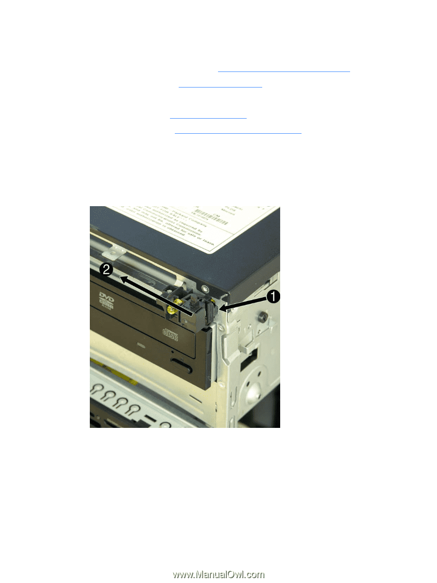
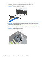
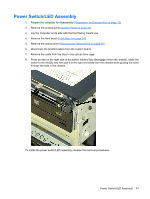
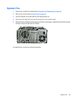
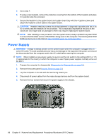
Power Switch/LED Assembly 1. Prepare the computer for disassembly (Preparation for Disassembly on page 32). 2. Remove the access panel (Access Panel on page 33). 3. Lay the computer on its side with the front facing toward you. 4. Remove the front bezel (Front Bezel on page 34). 5. Remove the optical drive (Removing an Optical Drive on page 49). 6. Disconnect the braided cables from the system board. 7. Remove the cable from the clips in the optical drive cage. 8. Press the tab on the right side of the switch holder (1) to disengage it from the chassis, rotate the switch to the left (2), and then pull it to the right and away from the chassis while guiding the wires through the hole in the chassis. To install the power switch/LED assembly, reverse the removal procedures. Power Switch/LED Assembly 61
-
 1
1 -
2
-
3
-
4
-
5
-
6
-
7
-
8
-
9
-
10
-
11
-
12
-
13
-
14
-
15
-
16
-
17
-
18
-
19
-
20
-
21
-
22
-
23
-
24
-
25
-
26
-
27
-
28
-
29
-
30
-
31
-
32
-
33
-
34
-
35
-
36
-
37
-
38
-
39
-
40
-
41
-
42
-
43
-
44
-
45
-
46
-
47
-
48
-
49
-
50
-
51
-
52
-
53
-
54
-
55
-
56
-
57
-
58
-
59
-
60
-
61
-
62
-
63
-
 64
64 -
 65
65 -
 66
66 -
 67
67 -
 68
68 -
 69
69 -
 70
70 -
 71
71 -
 72
72 -
 73
73 -
 74
74 -
75
-
76
-
77
-
78
-
79
-
80
-
81
-
82
-
83
-
84
-
85
-
86
-
87
-
88
-
89
-
90
-
91
-
92
-
93
-
94
-
95
-
96
-
97
-
98
-
99
-
100
-
101
-
102
-
103
-
104
-
105
 |
 |