HP nx6315 HP Compaq nx6315, nx6325 Notebook PC - Maintenance and Service Guide - Page 94
Preparing the Computer for Disassembly
 |
View all HP nx6315 manuals
Add to My Manuals
Save this manual to your list of manuals |
Page 94 highlights
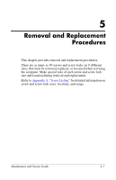
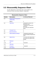
Removal and Replacement Procedures Disassembly Sequence Chart (Continued) Section 5.14 5.15 5.16 5.17 5.18 5.19 5.20 5.21 5.22 5.23 Description # of Screws Removed Mini Card WLAN Module 2 Å To prevent an unresponsive system and the display of a warning message, install only a Mini Card device authorized for use in your computer by the governmental agency that regulates wireless devices in your country. If you install a device and then receive a warning message, remove the device to restore computer functionality. Then contact Customer Care. Internal Memory Module 0 Switch Cover 2 Display Assembly 6 Top Cover 15 Speaker 0 Microphone 0 Modem Module 2 USB/Audio Board 1 System Board 2 screw locks 5.3 Preparing the Computer for Disassembly Before you begin any removal or installation procedures: 1. Shut down the computer. If you are unsure whether the computer is off or in hibernation, turn the computer on, and then shut it down through the operating system. 2. Disconnect all external devices connected to the computer. 3. Disconnect the power cord. 5-4 Maintenance and Service Guide
-
 1
1 -
2
-
3
-
4
-
5
-
6
-
7
-
8
-
9
-
10
-
11
-
12
-
13
-
14
-
15
-
16
-
17
-
18
-
19
-
20
-
21
-
22
-
23
-
24
-
25
-
26
-
27
-
28
-
29
-
30
-
31
-
32
-
33
-
34
-
35
-
36
-
37
-
38
-
39
-
40
-
41
-
42
-
43
-
44
-
45
-
46
-
47
-
48
-
49
-
50
-
51
-
52
-
53
-
54
-
55
-
56
-
57
-
58
-
59
-
60
-
61
-
62
-
63
-
64
-
65
-
66
-
67
-
68
-
69
-
70
-
71
-
72
-
73
-
74
-
75
-
76
-
77
-
78
-
79
-
80
-
81
-
82
-
83
-
84
-
85
-
86
-
87
-
88
-
 89
89 -
 90
90 -
 91
91 -
 92
92 -
 93
93 -
 94
94 -
 95
95 -
 96
96 -
 97
97 -
 98
98 -
 99
99 -
100
-
101
-
102
-
103
-
104
-
105
-
106
-
107
-
108
-
109
-
110
-
111
-
112
-
113
-
114
-
115
-
116
-
117
-
118
-
119
-
120
-
121
-
122
-
123
-
124
-
125
-
126
-
127
-
128
-
129
-
130
-
131
-
132
-
133
-
134
-
135
-
136
-
137
-
138
-
139
-
140
-
141
-
142
-
143
-
144
-
145
-
146
-
147
-
148
-
149
-
150
-
151
-
152
-
153
-
154
-
155
-
156
-
157
-
158
-
159
-
160
-
161
-
162
-
163
-
164
-
165
-
166
-
167
-
168
-
169
-
170
-
171
-
172
-
173
-
174
-
175
-
176
-
177
-
178
-
179
-
180
-
181
-
182
-
183
-
184
-
185
-
186
-
187
-
188
-
189
-
190
-
191
-
192
-
193
-
194
-
195
-
196
-
197
-
198
-
199
-
200
-
201
-
202
-
203
-
204
-
205
-
206
-
207
-
208
-
209
-
210
-
211
 |
 |