HP rp5800 Illustrated Parts & Service Map HP rp5800 Retail System - Page 2
Password Security, System Board - pci serial port
 |
View all HP rp5800 manuals
Add to My Manuals
Save this manual to your list of manuals |
Page 2 highlights
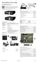
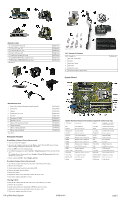
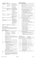
Expansion cards 1 2-port powered serial card 2 PCIe to PCI riser, 24V 3 Powered USB card, 12V 4 PCIe to PCI riser, 24V * eSATA port assembly, PCI card * Intel PRO/1000CT NIC, includes bracket * HP FireWire / IEEE 1394a PCIe x1 Card * Not shown 638947-001 638944-001 638945-001 638943-001 645558-001 635523-001 637591-001 50°C Thermal Kit Contents 50°C Thermal Kit 1 Heat sink, copper-base 2 Partition 3 Radial fan, 70mm 4 Fan holder 5 Vented slot covers 6 Front bezel trim (no optical drive) System Board 649033-001 Miscellaneous Parts 1 Heat sink (includes replacement thermal material) 2 Chassis fan 3 Speaker 4 Printer port, PCI card 5 Fan duct 6 Serial port (COMB) * Modem, LSI, v.92 * Mouse, PS2, optical, jack black * Mouse, washable * Mouse, optical, jack black * Mouse, laser, jack black *Not shown 645326-001 653024-001 636925-001 638817-001 636921-001 638946-001 490689-001 537748-001 619580-001 537749-001 570580-001 Password Security Establishing a Setup or Power-On password: 1. Turn on or restart the computer. 2. As soon as the computer turns on, press the Esc key while "Press the ESC key for Startup Menu" message is displayed at the bottom of the screen. 3. Press the F10 key to enter Computer Setup. 4. To establish Setup password, select Security > Setup Password and follow the instructions. - or To establish a Power-On password, select Security > Power-On Password and follow the instructions on the screen 5. Before exiting, click File > Save Changes and Exit. Resetting a Setup or Power-On password: 1. Turn off the computer and disconnect the power cord from the power outlet. 2. Remove the access panel. 3. On the system board, locate the header labeled E49. 4. Remove the jumper from the header. 5. Replace the jumper. 6. Replace the chassis access panel and reconnect the power cord. 7. Turn on the computer and allow it to start. Clearing CMOS 1. Turn off the computer and disconnect the power cord from the power outlet. 2. Remove the access panel. 3. On the system board, press and hold the CMOS button for 5 seconds. 4. Replace the chassis access panel and reconnect the power cord. 5. Turn on the computer and allow it to start. System Board Connectors and Jumpers (component location may vary) X1PCIEXP1 PCIe X1 slot SATA1 2nd HDD, or 1st ODD if eSATA Adapter exists BAT RTC battery slot 12VUSB2 Powered USB connector CHFAN Main fan connector PWR Main power connector PROCESSOR Processor socket 12VUSB1 Powered USB connector CHFAN2 50C fan connector PWRCMD Power connector PWRCPU CPU power connector PSWD Password header XMM4 Memory socket - Channel B IN/OUT Audio connectors XMM3 Memory socket - Channel B PS2 PS/2 connectors XMM2 Memory socket - Channel A COMB Serial port XMM1 Memory socket - Channel A VGA COM Monitor connectors ESATA eSATA/ODD connector PAR Parallel port connector SPKR Speaker connector USB USB connectors FRONT_USB USB connector 12VUSB3 Powered USB connector SATA PWR SATA drive power connector RJ45/USB Network/USB connector FRNT AUD Front panel connector DISPLAYPORT DisplayPort connector FRONT_USB2 2nd USB connector RPOS RISER Riser card connector SATA0 1st hard drive X16PCIEXP PCIe X16 slot HP rp5800 Retail System 659816-001 page 2
-
 1
1 -
 2
2 -
 3
3
 |
 |
