HP t5630 Troubleshooting Guide: HP t5630, t5545, t5145, and t5540 Thin Clients - Page 18
Removing and Replacing the Side Access Panel and Metal Side Cover
 |
View all HP t5630 manuals
Add to My Manuals
Save this manual to your list of manuals |
Page 18 highlights
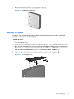
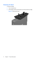
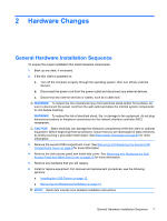
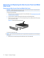
Removing and Replacing the Side Access Panel and Metal Side Cover Removing the Side Access Panel and Metal Side Cover WARNING! Before removing the side access panel, ensure that the thin client is turned off and the power cord is disconnected from the electrical outlet. To remove the access panel: 1. Remove the secure compartment cover (1). For more information, see Removing the Secure USB Compartment Cover on page 8. 2. Lay the unit flat on a stable surface with the right side up and the left side down. 3. Slide the access panel about 3 mm (1/8 inch) toward the top of the unit (2), and then lift the access panel up and off the unit (3). Figure 2-3 Removing the side access panel To remove the metal side cover: NOTE: You must remove the metal side cover to access internal components such as the battery or the memory. 1. Remove the four screws that secure the metal side cover to the chassis (1). 10 Chapter 2 Hardware Changes
-
 1
1 -
2
-
3
-
4
-
5
-
6
-
7
-
8
-
9
-
10
-
11
-
12
-
 13
13 -
 14
14 -
 15
15 -
 16
16 -
 17
17 -
 18
18 -
 19
19 -
 20
20 -
 21
21 -
 22
22 -
 23
23 -
24
-
25
-
26
-
27
-
28
-
29
-
30
-
31
-
32
-
33
-
34
-
35
-
36
-
37
-
38
-
39
-
40
-
41
-
42
-
43
-
44
-
45
-
46
-
47
-
48
-
49
-
50
-
51
-
52
-
53
-
54
-
55
-
56
-
57
-
58
-
59
-
60
-
61
-
62
-
63
-
64
-
65
-
66
-
67
-
68
-
69
-
70
-
71
-
72
-
73
 |
 |
