Hitachi CPRS55 Operating Guide - Page 3
Connection to the ports
 |
UPC - 050585150690
View all Hitachi CPRS55 manuals
Add to My Manuals
Save this manual to your list of manuals |
Page 3 highlights
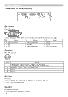
Connection to the ports Technical (continued) CONTROL RGB 1 K S-VIDEO VIDEO AUDIO 1 RGB D-sub 15pin mini shrink jack 11 12 13 14 15 6 7 8 9 10 12 345 At RGB signal • Video signal: RGB separate, Analog, 0.7Vp-p, 75Ω terminated (positive) • H/V. sync. Signal: TTL level (positive/negative) • Composite sync. Signal: TTL level At component video signal • System: 525i (480i), 525p (480p), 625i (576i), 750p (720p), 1125i (1080i) At RGB signal Pin Signal 1 Video Red 2 Video Green 3 Video Blue 4 (No connection) 5 Ground 6 Ground Red 7 Ground Green 8 Ground Blue 9 (No connection) 10 Ground 11 (No connection) 12 SDA (DDC data) 13 H. sync / Composite sync. 14 V. sync. 15 SCL (DDC clock) At component video signal Pin Signal 1 CR/PR 2Y 3 CB/PB 4 (No connection) 5 Ground 6 CR/PR Ground 7 Y Ground 8 CB/PB Ground 9 (No connection) 10 Ground 11 (No connection) 15 * except for RGB OUT. 3
-
 1
1 -
 2
2 -
 3
3 -
 4
4 -
 5
5 -
 6
6 -
 7
7 -
 8
8 -
 9
9 -
10
-
11
-
12
 |
 |
