Hitachi CPS240 Technical Operating Manual - Page 3
RGB IN1, RGB IN2, RGB OUT, Except when set to RGB - usb
 |
UPC - 050585160781
View all Hitachi CPS240 manuals
Add to My Manuals
Save this manual to your list of manuals |
Page 3 highlights
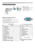
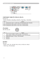
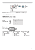
Connection to the ports Connection to the ports AUDIO IN2 Y R CB/PB L CR/PR VIDEO S-VIDEO CONTROL AUDIO OUT AUDIO IN1 A B RGB IN1 RGB IN2 RGB OUT USB K RGB IN OUT switch When this switch is not pushed in, RGB IN2 is selected. When this switch is pushed in, RGB OUT is selected. A RGB IN1, B RGB IN2, RGB OUT D-sub 15pin mini shrink jack • Video signal: RGB separate, Analog, 0.7Vp-p, 75Ω terminated (positive) • H/V. sync. Signal: TTL level (positive/negative) • Composite sync. Signal: TTL level At RGB signal Pin Signal 1 Video Red 2 Video Green 3 Video Blue 4 (No connection) 5 Ground 6 Ground Red 7 Ground Green 8 Ground Blue 9 (No connection) 10 Ground 11 (No connection) 12 A : SDA (DDC data), B 13 H. sync / Composite sync. 14 V. sync. 15 A : SCL (DDC clock), B 54 321 10 9 8 7 6 15 14 13 12 11 At component video signal Pin Signal 1 CR/PR 2Y 3 CB/PB 4 (No connection) 5 Ground 6 CR/PR Ground 7 Y Ground 8 CB/PB Ground 9 (No connection) 10 Ground 11 (No connection) 15 * B Except when set to RGB OUT 3
-
 1
1 -
 2
2 -
 3
3 -
 4
4 -
 5
5 -
 6
6 -
 7
7 -
 8
8 -
 9
9 -
10
-
11
-
12
-
13
-
14
 |
 |
