Hitachi CPX2510 Technical Manual
Hitachi CPX2510 - XGA LCD Projector Manual
 |
UPC - 050585151680
View all Hitachi CPX2510 manuals
Add to My Manuals
Save this manual to your list of manuals |
Hitachi CPX2510 manual content summary:
- Hitachi CPX2510 | Technical Manual - Page 1
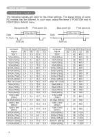
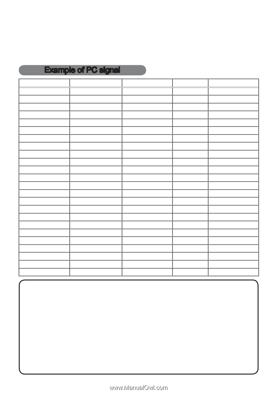
Projector CP-X2010/CP-X2510/CP-X3010 User's Manual (detailed) Operating Guide - Technical Example of PC signal Resolution (H x V) H. frequency ( and projector panel are identical. • Automatic adjustment may not function correctly with some input signals. • The image may not be displayed correctly - Hitachi CPX2510 | Technical Manual - Page 2
timing of some PC models may be different. In such case, adjust the items V POSITION and H POSITION in IMAGE menu. Back porch (B) Front porch (D) Data H. Sync. Active video (C) Sync (A) Back porch (b) Front porch (d) Data V. Sync. Active video (c) Sync (a) computer Horizontal signal timing - Hitachi CPX2510 | Technical Manual - Page 3
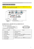
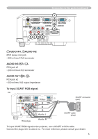
cables with straight plugs, not L-shaped ones, as the input ports of the projector are recessed. C B A A COMPUTER IN1, B COMPUTER IN2, C MONITOR 2 Video Green 3 Video Blue 4 (No connection) 5 Ground Pin 9 (No connection) Signal 10 Ground 11 (No connection) 12 A : SDA (DDC data) / B , C : - Hitachi CPX2510 | Technical Manual - Page 4
DE F H COMPONENT D Y, E Cb/Pb F Cr/Pr RCA jack x3 • System: 480i@60, 480p@60, 576i@50, 720p@50/60, 1080i@50/60 Port Signal 2 Brightness signal, 1.0Vp-p, 75Ω terminator 3 Ground 4 Ground H VIDEO RCA jack • System: NTSC, PAL, SECAM, PAL-M, PAL-N, NTSC4.43, PAL60 • 1.0±0.1Vp-p, 75Ω terminator 4 - Hitachi CPX2510 | Technical Manual - Page 5
mVrms 1kΩ output impedance To input SCART RGB signal; ex.: RCA plugs SCART connector (jack) SCART cable (plug) To input SCART RGB signal to the projector, use a SCART to RCA cable. Connect the plugs refer to above ex.. For more reference, please consult your dealer. 5 - Hitachi CPX2510 | Technical Manual - Page 6
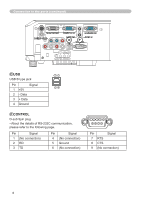
Connection to the ports (continued) O P O USB 21 USB B type jack Pin Signal 34 1 +5V 2 - Data 3 + Data 4 Ground P CONTROL D-sub 9pin plug • About the details of RS-232C communication, please refer to the following page. Pin Signal 1 (No connection) 2 RD 3 TD Pin - Hitachi CPX2510 | Technical Manual - Page 7
the previous page. Turn the computer on, and after the computer has started up turn the 3. projector on. Communications setting 19200bps, 8N1 1. Protocol Consist of header (7 bytes) + command data (6 bytes) 2. Header BE + EF + 03 + 06 + 00 + CRC_low + CRC_high CRC_low: Lower byte of CRC flag for - Hitachi CPX2510 | Technical Manual - Page 8
be guaranteed when the projector receives an undefined command or data. • Provide an interval of at least 40ms between the response code and any other code. • The projector outputs test data when the power supply is switched ON, and when the lamp is lit. Ignore this data. • Commands are not accepted - Hitachi CPX2510 | Technical Manual - Page 9
command table Names Power Operation Type Set Get Increment Decrement Execute Get Increment Decrement Execute Header Command Data CRC Action Type Setting Code BE EF 03 06 00 error] 03 00 [Lamp error] 04 00 [Temp error] 05 00 [Air flow error] 07 00 [Cold error] 08 00 [Filter error] BE EF 03 - Hitachi CPX2510 | Technical Manual - Page 10
User Gamma Point 1 User Gamma Point 1 Reset User Gamma Point 2 User Gamma Point 2 Reset User Gamma Point 3 User Gamma Point 3 Reset User Gamma Point 4 User Gamma Point 4 Reset User Gamma Point 5 User Gamma Point 5 Reset User Gamma Point 6 User Gamma Point 6 Reset User Gamma Point 7 User Command Data - Hitachi CPX2510 | Technical Manual - Page 11
RS-232C Communication command table (continued) Names Operation Type User Gamma Point 8 User Gamma Point 8 Reset COLOR TEMP Set COLOR TEMP GAIN R COLOR TEMP GAIN R Reset 40 F5 26 F5 F7 F4 BC C4 BC F4 DA F4 0B F5 C8 C5 Command Data Action Type Setting Code 02 00 04 00 05 00 06 00 01 00 01 00 01 - Hitachi CPX2510 | Technical Manual - Page 12
RS-232C Communication command table (continued) Names Operation Type Header Command Data CRC Action Type Setting Code COLOR COLOR Reset TINT TINT Reset SHARPNESS SHARPNESS Reset ACTIVE 00 00 00 00 00 00 00 * ACTIVE IRIS is available only for CP-X2510 and CP-X3010. (continued on next page) 12 - Hitachi CPX2510 | Technical Manual - Page 13
52 75 52 70 62 77 C2 71 32 74 31 76 CE D6 5E D7 0D D6 32 D7 A2 D6 F1 D7 Command Data Action Type Setting Code 02 00 04 00 05 00 06 00 02 21 02 21 02 21 04 70 00 00 00 00 00 - Hitachi CPX2510 | Technical Manual - Page 14
Operation Type FRAME LOCK - Set COMPUTER1 FRAME LOCK - Set COMPUTER2 AUTO KEYSTONE V EXECUTE KEYSTONE V KEYSTONE V Reset ECO MODE Set MIRROR Set STANDBY MODE Set MONITOR OUT - 2A F7 EA F5 DA B6 19 F7 CD CC AB CC 7A CD Command Data Action Type Setting Code 01 00 01 00 02 00 01 00 01 00 02 - Hitachi CPX2510 | Technical Manual - Page 15
32 DD 01 DD D6 DD 26 DD B6 DC 46 DC 75 DC 92 DD 62 DD F2 DC 02 DC 31 DC Command Data Action Type Setting Code 02 00 04 00 05 00 02 00 04 00 05 00 02 00 04 00 05 00 02 00 04 - Hitachi CPX2510 | Technical Manual - Page 16
MENU POSITION V Reset Execute BE EF 03 06 00 * Not all of the languages in the table are supported. CRC 7A DF 8A DF 1A DE EA DE D9 DE F7 D3 67 D2 97 D2 07 D3 37 C4 D3 04 D7 62 D7 B3 D6 DC C6 40 D7 26 D7 F7 D6 A8 C7 Command Data Action Type Setting Code 01 00 01 00 01 00 01 00 02 00 01 00 01 00 - Hitachi CPX2510 | Technical Manual - Page 17
Set C. C. - MODE Set C. C. - CHANNEL Set AUTO SEARCH Set AUTO KEYSTONE Set DIRECT ON Set MyScreen ORIGINAL BLUE WHITE BLACK Get OFF ON Get MyScreen ORIGINAL OFF Get OFF ON Get OFF ON D6 EA D1 7A D0 D9 D1 3B 89 AB 88 08 89 Command Data Action Type Setting Code 01 00 00 30 20 00 01 00 00 30 - Hitachi CPX2510 | Technical Manual - Page 18
Data CRC Action Type Setting Code AUTO OFF Get BE EF 03 Increment BE EF 03 Decrement BE EF 03 LAMP TIME Get BE EF 03 LAMP TIME Reset Execute BE EF 03 FILTER TIME Get BE EF 03 FILTER BE EF 03 REMOTE FREQ. Set OFF NORMAL ON BE EF 03 BE EF 03 Get BE EF 03 REMOTE FREQ. Set OFF
-
 1
1 -
 2
2 -
 3
3 -
 4
4 -
 5
5 -
 6
6 -
 7
7 -
8
-
9
-
10
-
11
-
12
-
13
-
14
-
15
-
16
-
17
-
18
 |
 |
1
Projector
CP-X2010/CP-X2510/CP-X3010
User's Manual (detailed)
Operating Guide – Technical
Resolution (H x V)
H. frequency (kHz)
V. frequency (Hz)
Rating
Signal mode
720 x 400
37.9
85.0
VESA
TEXT
640 x 480
31.5
59.9
VESA
VGA (60Hz)
640 x 480
37.9
72.8
VESA
VGA (72Hz)
640 x 480
37.5
75.0
VESA
VGA (75Hz)
640 x 480
43.3
85.0
VESA
VGA (85Hz)
800 x 600
35.2
56.3
VESA
SVGA (56Hz)
800 x 600
37.9
60.3
VESA
SVGA (60Hz)
800 x 600
48.1
72.2
VESA
SVGA (72Hz)
800 x 600
46.9
75.0
VESA
SVGA (75Hz)
800 x 600
53.7
85.1
VESA
SVGA (85Hz)
832 x 624
49.7
74.5
Mac 16” mode
1024 x 768
48.4
60.0
VESA
XGA (60Hz)
1024 x 768
56.5
70.1
VESA
XGA (70Hz)
1024 x 768
60.0
75.0
VESA
XGA (75Hz)
1024 x 768
68.7
85.0
VESA
XGA (85Hz)
1152 x 864
67.5
75.0
VESA
1152 x 864 (75Hz)
1280 x 768
47.7
60.0
VESA
W-XGA (60Hz)
1280 x 800
49.7
60.0
VESA
1280 x 800 (60Hz)
1280 x 960
60.0
60.0
VESA
1280 x 960 (60Hz)
1280 x 1024
64.0
60.0
VESA
SXGA (60Hz)
1280 x 1024
80.0
75.0
VESA
SXGA (75Hz)
1280 x 1024
91.1
85.0
VESA
SXGA (85Hz)
1400 x 1050
65.2
60.0
VESA
SXGA+ (60Hz)
1600 x 1200
75.0
60.0
VESA
UXGA (60Hz)
NOTE
• Be sure to check jack type, signal level, timing and resolution
before connecting this projector to a PC.
• Some PCs may have multiple display screen modes. Use of some of these
modes will not be possible with this projector.
• Depending on the input signal, full-size display may not be possible in some
cases. Refer to the number of display pixels above.
• Although the projector can display signals with resolution up to UXGA
(1600x1200), the signal will be converted to the projector’s panel resolution
before being displayed. The best display performance will be achieved if the
resolutions of the input signal and projector panel are identical.
• Automatic adjustment may not function correctly with some input signals.
• The image may not be displayed correctly when the input sync signal is a
composite sync or a sync on G.
Example of PC signal