Hitachi SV13YB Instruction Manual - Page 11
Installing the sanding paper, Attaching and removing the dust bag, Adjustment of speed SV13YA only - hook and loop pad
 |
UPC - 717709009967
View all Hitachi SV13YB manuals
Add to My Manuals
Save this manual to your list of manuals |
Page 11 highlights
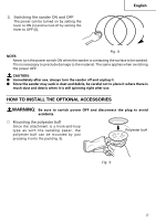
6. Installing the sanding paper Since the attachment is a hook-and-loop type, the sanding paper can be installed easily by just pressing it onto the pad. When installing the sanding paper, in order to match it to the holes in the pad, gently fold it along the axis of two holes as shown in Fig. 3. Next, use the holes along the fold as a guide to match the sanding paper and the pad. Finally, press the entire sanding paper uniformly onto the pad. 7. Attaching and removing the dust bag (1) Attaching the dust bag As shown in Fig. 4, hold the dust gate and push it in the direction of arrow A to attach it to the dust outlet. (2) Removing the dust bag As shown in Fig. 4, hold the dust gate and pull it in the direction of arrow B to remove it from the dust outlet. 8. Adjustment of speed (SV13YA only) The SV13YA is equipped with the electric control circuit which enables non-step speed control. To adjust the speed, turn the dial shown in Fig. 5. When the dial is set to "1", the sander operates at the minimum speed (7,000/min). When the dial set to "6", the sander operates at the maximum speed (12,000/min). Adjust the speed according to the material to be cut and working efficiency. Sanding paper Pad English Fig. 3 A B Dust bag Dust gate Dust outlet Fig. 4 Dial Fig. 5 11
-
 1
1 -
2
-
3
-
4
-
5
-
 6
6 -
 7
7 -
 8
8 -
 9
9 -
 10
10 -
 11
11 -
 12
12 -
 13
13 -
 14
14 -
 15
15 -
 16
16 -
17
-
18
-
19
-
20
-
21
-
22
-
23
-
24
-
25
-
26
-
27
-
28
-
29
-
30
-
31
-
32
-
33
-
34
-
35
-
36
-
37
-
38
-
39
-
40
-
41
-
42
-
43
-
44
 |
 |
