Hitachi W6VB3SD Instruction Manual - Page 9
Functional Description - screws
 |
UPC - 754005008720
View all Hitachi W6VB3SD manuals
Add to My Manuals
Save this manual to your list of manuals |
Page 9 highlights
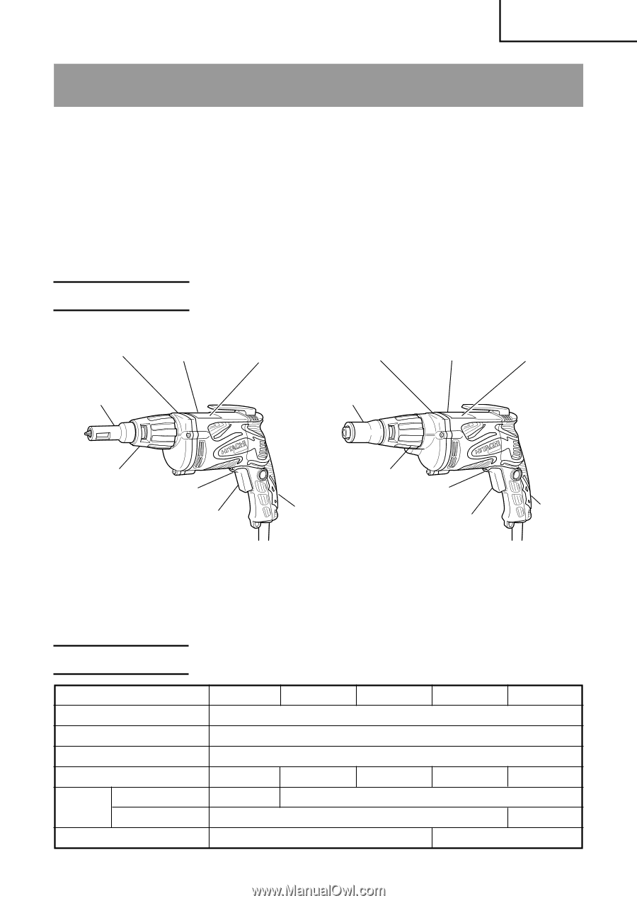
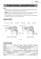
English FUNCTIONAL DESCRIPTION NOTE: The information contained in this Instruction Manual is designed to assist you in the safe operation and maintenance of the power tool. NEVER operate, or attempt any maintenance on the tool unless you have first read and understood all safey instructions contained in this manual. Some illustrations in this Instruction Manual may show details or attachments that differ from those on your own power tool. NAME OF PARTS Gear Cover Housing Nameplate Gear Cover Housing Nameplate Sub-Stopper (F) Sub-Stopper (B) Locator Lever Switch W6VM • W6V4 • W6VA4 Locator Handle Cover Lever Switch Handle Cover Fig. 1 W6VB3 • W8VB2 SPECIFICATIONS Model W6VM W6V4 W6VA4 W6VB3 W8VB2 Motor Single-Phase, Series Commutator Motor Power Source Single-Phase, 120 V 60 Hz Current 6.5 A No-Load Speed 0-6000/min. 0-4500/min. 0-3000/min. 0-2600/min. 0-1700/min. Capacity Drywall screw 3/16" (5 mm) Self-drilling screw 1/4" (6 mm) 1/4" (6 mm) 5/16" (8 mm) Weight 3.1 lbs (1.4 kg) 3.3 lbs (1.5 kg) 9
-
 1
1 -
2
-
3
-
 4
4 -
 5
5 -
 6
6 -
 7
7 -
 8
8 -
 9
9 -
 10
10 -
 11
11 -
 12
12 -
 13
13 -
 14
14 -
15
-
16
-
17
-
18
-
19
-
20
-
21
-
22
-
23
-
24
-
25
-
26
-
27
-
28
-
29
-
30
-
31
-
32
-
33
-
34
-
35
-
36
-
37
-
38
-
39
-
40
-
41
-
42
-
43
-
44
-
45
-
46
-
47
-
48
-
49
-
50
-
51
-
52
-
53
-
54
-
55
-
56
 |
 |