Hitachi WR16SA Instruction Manual - Page 11
HOW TO USE - impact
 |
UPC - 717709009035
View all Hitachi WR16SA manuals
Add to My Manuals
Save this manual to your list of manuals |
Page 11 highlights
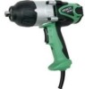
English 7. Mounting the socket (Fig.2) Align the plunger located in the square part of the anvil with the hole in the hex. socket. Then push the plunger, and mount the hex. socket on the anvil. Check that the plunger is fully engaged in the hole. When removing the socket, reverse the sequence. HOW TO USE 1. Operation of switch (Fig.3) The switch in this machine functions as a motor switch and rotational direction selector switch. When the switch is set to R indicated on the handle cover, the motor rotates clockwise to tighten the bolt. When the switch is set to L, the motor rotates counterclockwise to loosen the bolt. When the switch is released, the motor stops. Plunger Hole Hex. socket Anvil Fig. 2 Switch Fig. 3 CAUTION: Be sure to turn the switch OFF and wait until the motor completely stops before changing the direction of wrench revolution. Switching while the motor is rotating will result in burning the motor. 2. Tightening and loosening bolts A hex. socket matching the bolt or nut must first be selected. Then mount the socket on the anvil, and grip the nut to be tightened with the hex. socket. Holding the wrench in line with the bolt, press the power switch to impact the nut for several seconds. If the nut is only loosely fitted to the bolt, the bolt may turn with the nut, therefore preventing proper tightening. In this case, stop impact on the nut and hold the bolt head with a wrench before restarting impact, or manually tighten the bolt and nut to prevent them slipping. 11
-
 1
1 -
2
-
3
-
4
-
5
-
 6
6 -
 7
7 -
 8
8 -
 9
9 -
 10
10 -
 11
11 -
 12
12 -
 13
13 -
 14
14 -
 15
15 -
 16
16 -
17
-
18
-
19
-
20
-
21
-
22
-
23
-
24
-
25
-
26
-
27
-
28
-
29
-
30
-
31
-
32
-
33
-
34
-
35
-
36
-
37
-
38
-
39
-
40
-
41
-
42
-
43
-
44
-
45
-
46
-
47
-
48
 |
 |
