Hitachi X1250 Lens Replacement Manual - Page 2
instructions
 |
UPC - 050585150638
View all Hitachi X1250 manuals
Add to My Manuals
Save this manual to your list of manuals |
Page 2 highlights
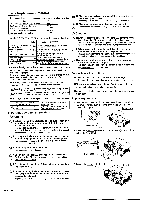
4. Remove the lens. (1) Open the lens door. (2) Press the lens release lever. (3) Rotate the lens counterclockwise and pull it out. (1) Ji 1 (2) Detailed drawing of the lever (3) Important instructions when removing the lens: 1. Do not touch the prism area at the rear of the lens. 2. Do not touch the terminals. 3. Do not pull the wires. 5. Mount the replacement lens. (1) Align the red mark on the lens with the red mark on the lens holder and insert the lens into the holder. (2) Turn the lens clockwise until a click is heard, Attach the lens so that the red mark on the lens and the green mark on the holder are aligned. (3) Confirm that the lens is securely locked. (4) After replacing the lens, make sure that the connector for the shift motor is firmly set in place. (3) b. Connector for the shift motor , (2),(2 6. Close the lens door and tighten the screw. 7. Reattach the front panel. (1) Place the front panel on the projector. 8. Reattach the lamp cover to complete the lens replacement. (1) Align the two tabs on the lamp cover with the receiving areas on the projector. (2) Press the lamp cover into place at the three indicated locations. (1) (2) \ a ) 9. Attach the louver. (Only for models FL-501 and SL-502) Note: The louver is designed for use with Short Throw Fixed and Short Throw Zoom lenses. It minimizes disruption of the projected image caused by projector heat exhaust. (1) Attach the five tabs located on the top and side of the louver to the groove that runs along the 46. top and front side Nr" Larger scale image of of the projector. the projector front bottom • • 0 ri (Larger scale image) Louver (2) Insert the bottom of the louver into the depression where the screw is located. Note: When removing the louver, lift the louver diagonally while pressing the protrusion on the bottom. 10. Confirm that the louver is securely attached. (Only for models FL-501 and SL-502) Note: If the projector is installed at a high location, be sure to attach the louver cord to the shaft of the elevator foot. This prevents the louver from slipping from a the projector. Louver - String - Elevator foot 11. When the projector is not in use, attach the supplied lens cap to protect the lens surface. (Only for models LL-503 and UL-504) I(2) Secure it with the two screws on the bottom of the projector. r0 j • • Note: For models, FL-501 and SL-502, use the lens cap supplied with the projector. IJ Fasten by passing a string through the bottom clamp. Also, if not required, DI remove the currently attached standard lens cap.
-
 1
1 -
 2
2
 |
 |
