Honeywell 50045947 Owner's Manual - Page 5
RO System with, Storage Tank - controls
 |
View all Honeywell 50045947 manuals
Add to My Manuals
Save this manual to your list of manuals |
Page 5 highlights
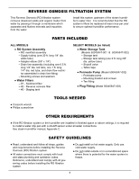
PLUMBING RO System with Storage Tank To Steam Shutoff Humidifier Control Valve (Model 50045947-001) Cold Water Supply Drain Points for Reject Water Follow local codes for proper installation Refer to additional drain requirements in steam humidifier manual when coupling RO drain and humidifier drain 1/4" Red Tubing 1/4" White Tubing 1/4" White Tubing 3/8" x 1/4" Adapter Elbow Closed Open 3/8" Yellow Tubing Sump air gap Standpipe air gap air gap air gap Laundry Tub Floor Drain #1 #2 #3 Drain Flow Control Storage Tank FIG. 3 air gap Condensate Pump Floor Drain Cut 1/4" dia. tubing lines to fit your installation. Ensure all cuts are evenly made with no nicks, scratches or rough spots on the tube end. Longer tubing lengths - nylon or copper - may also be used (not provided). Ends of tubing must be round and free of burrs and scratches to seal properly. Install 3/8" x 1/4" adapter elbow into blue outlet port. Install 3/8" dia. yellow tube between yellow inlet port and storage tank valve (Models 50045947001 & 50045947-002). Insert plug from parts bag in yellow port for Model 50045947-003. Locate drain line assembly (1/4" dia. red tubes assembled to flow control coupling). Install 1 ft. long end of 1/4" dia. red drain line into red port in the RO system. Route the longer 1/4" dia. red drain line to a drain. Note that the coupling contains a flow control that is critical to the function of the RO system. Make sure the drain line assembly is installed correctly. Push tubing completely into applicable fitting by pushing past initial resistance and then applying light pulling force to ensure a tight fit. Tubing Collar O-Ring Tube Fully Engaged with Fitting FIG. 4 - To remove tube from connection, depress collar and pull tubing. Collar (depress to remove tubing) Tubing FIG. 5 Water tube connections to the water supply, filter and steam humidifier must be checked for leaks after installation and a short period of operation. 5
-
 1
1 -
 2
2 -
 3
3 -
 4
4 -
 5
5 -
 6
6 -
 7
7 -
 8
8 -
 9
9 -
 10
10 -
 11
11 -
12
-
13
-
14
-
15
-
16
-
17
-
18
-
19
-
20
-
21
-
22
-
23
-
24
 |
 |
