Honeywell 5800PIR-RES Installation Instructions
Honeywell 5800PIR-RES Manual
 |
View all Honeywell 5800PIR-RES manuals
Add to My Manuals
Save this manual to your list of manuals |
Honeywell 5800PIR-RES manual content summary:
- Honeywell 5800PIR-RES | Installation Instructions - Page 1
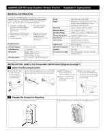
5800PIR-OD Wireless Outdoor Motion Sensor - Installation Instructions GENERAL INFORMATION The Honeywell 5800PIR-OD Wireless Outdoor Motion Sensor (referred to as the 5800PIR-OD) combines the convenience of wireless technology with a full featured outdoor PIR motion sensor. The major features are - Honeywell 5800PIR-RES | Installation Instructions - Page 2
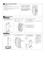
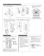
of battery is pointing away from the springs. 4 Mount the Sensor WALL MOUNTING 1. Install the Back Box on the wall using two M4 x 20 mounting screws. 2. Secure the Detector to the Back Box. 3. Fasten with four self tapping M3 x 14 screws. 4. Perform Settings & Adjustments. 5. Perform a Walk Test - Honeywell 5800PIR-RES | Installation Instructions - Page 3
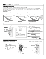
not made. Press and slide the Detection Length Adjustment Switch to the desired position. Default Setting D C B A DETECTION LENGTH D 02.0m (6.7ft) C 05.0m (16.7ft) B 08.0m (26.7ft) A 12.0m (40.0ft) NOTES: • This table is based on a motion sensor height of 1m (3.3ft) • The height of the - Honeywell 5800PIR-RES | Installation Instructions - Page 4
prevent false detections. High sensitivity - Best detection catches (increased false detections). Use for applications where you are tagging video, or need high security awareness. SET THE DIP SWITCHES 1. At the DIP switches, set switch 2 for the desired Battery Saving Timer period. Note: The alarm - Honeywell 5800PIR-RES | Installation Instructions - Page 5
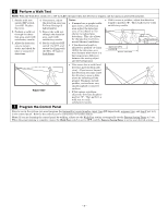
cause the detector to issue a false alarm by reflecting off the ground. Examples include puddles, wet surfaces, very smooth asphalt or concrete surfaces. ƒ If this causes a problem, adjust the detection length to position "B". Then perform a walk test to verify satisfactory results. 7 Program the - Honeywell 5800PIR-RES | Installation Instructions - Page 6
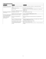
are incorrectly installed or dead. Wiring is faulty or loose. Water in unit. No detection occasionally, or poor detection. Low battery fault indicated on system keypad display. Alarms when no one is walking through the detection area. Transmitter or PIR sensor is faulty. Sensitivity is set - Honeywell 5800PIR-RES | Installation Instructions - Page 7
COMPONENT IDENTIFICATION DIAGRAM Pole Bracket Back Box Use four M4x30 screws if mounting to pole brackets, or two M4x20 screws if mounting to wall. UP Sensor (Do not touch) Cover LED Indicator DIP Switch Sensitivity Select Switch Detection Length Ajustment Switch Transmitter Lens Holder - Honeywell 5800PIR-RES | Installation Instructions - Page 8
. INFORMATION TO USER Unauthorized changes or modifications could void the user's authority to operate the equipment. DOCUMENTATION AND ONLINE SUPPORT For the latest documentation and online support information, please go to: http://www.security.honeywell.com/hsc/resources/MyWebTech/ WARRANTY
-
 1
1 -
 2
2 -
 3
3 -
 4
4 -
 5
5 -
 6
6 -
 7
7 -
8
 |
 |

5800PIR-OD Wireless Outdoor Motion Sensor –
Installation Instructions
GENERAL INFORMATION
The Honeywell 5800PIR-OD Wireless Outdoor Motion Sensor
(referred to as the 5800PIR-OD) combines the convenience of
wireless technology with a full featured outdoor PIR motion
sensor.
The major features are highlighted below:
Immunity to bright light
disturbances from headlights,
sunlight, and other bright
light sources.
Selectable detector
range and angle.
Discriminates both large and
small animals to reduce false
alarms.
Tamper detection.
Battery saving circuit
allows for a 5 or 120
second period of
inactivity before being
reactivated.
SPECIFICATIONS
Detection Method
Passive Infrared
Initial Warm Up
~ 2 minutes
Dimensions
Height 199mm
(7.8 in.)
Width 82mm
(3.2 in.)
Depth 120mm
(4.7 in.)
Mounting Height
0.8 - 1.2m (2.7 - 4ft) To the center of
lens.
Range
Adjustable up to 12m (40ft)
Pattern
90
°
pattern consisting of 13 zones.
This
pattern can be adjusted in 15
°
incre-
ments from center up to 45
°
.
Sensitivity
2.0
°
C at 0.6m/s (3.6
°
F at 2.0ft/s)
Detection Speed
0.3 - 1.5m/s (1 - 5ft/s)
Operating Voltage
6 VDC (uses 4 lithium 1.5VDC AA cells)
Battery Saving Timer
Adjustable 120sec or 5sec
Alarm Period
~ 2.5 seconds
LED Indicator
Enabled during a walk test.
Disabled for normal operation.
Weatherproof
IP54 compliance
Operating Temperature
– 20 to + 50
°
C (– 4 to +122
°
F)
Humidity
95% Max
Accessories (included)
Pole mounting kit, screw kit, detection
masking strips.
INSTALLATION
(refer to the Component Identification Diagram on page 7)
1
Select the Mounting Position
Avoid strong sunlight into the sensor's field.
Avoid moving or swaying trees and bushes.
Orient the detector
so that intrusion
passes across the
detection field, not
into the sensor.
Allow 110mm (4.4")
above the sensor to
enable opening the cover.
Choose an installation
height of 0.8m to 1.2m
(2.7 to 4ft).
Ensure the sensor can be
mounted on a perpendicular
wall or pole that would make
its detection pattern parallel
to the ground.
Parallel
2
Prepare the Sensor for Mounting
1.
Remove the Cover
by pulling from bottom.
2.
Remove Detector
from the Back Box
by pulling from top.