Honeywell 5800PIR-RES Installation Instructions - Page 2
Install / Replace the Battery, Mount the Sensor
 |
View all Honeywell 5800PIR-RES manuals
Add to My Manuals
Save this manual to your list of manuals |
Page 2 highlights
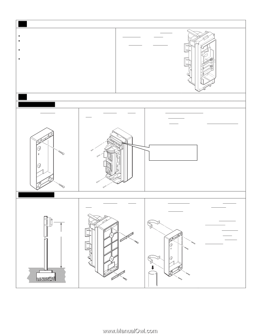
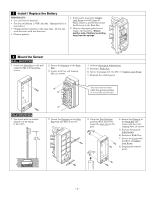
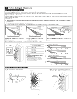
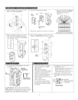
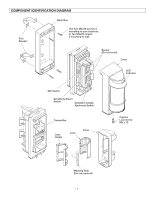
3 Install / Replace the Battery IMPORTANT: ƒ Use only lithium batteries. ƒ Use four (4) lithium 1.5VDC AA cells. (Energizer L91 or equivalent.) ƒ Change all four batteries at the same time. Do not mix weak batteries with new batteries. ƒ Observe polarity. 1. If necessary, loosen the Captive Lock Screw and lift Cover off. Then, remove 4 screws that secure the Detector to the Back Box. 2. Observe the proper polarity and replace the batteries. Ensure positive side of battery is pointing away from the springs. 4 Mount the Sensor WALL MOUNTING 1. Install the Back Box on the wall using two M4 x 20 mounting screws. 2. Secure the Detector to the Back Box. 3. Fasten with four self tapping M3 x 14 screws. 4. Perform Settings & Adjustments. 5. Perform a Walk Test. 6. Secure the Cover with the M3 x 10 Captive Lock Screw. 7. Program the control panel. You may have to move UP aside the sponge packing to reveal the screw holes. POLE MOUNTING 1. Use a pole with an outside diameter of 43-48mm (1.69-1.89"). 2.7- 4ft. 0.8 - 1.2m 2. Attach the Brackets to the Back Box with two M3 x 8 screws. 3. Using the Pole Brackets and four M4 x 30 screws, fasten the Back Box to the pole. UP 4. Secure the Detector to the Back Box and fasten with four selftapping M3 x 14 screws. 5. Perform Settings & Adjustments. 6. Perform a Walk Test. 7. Secure the Cover with the M3 x 10 Captive Lock Screw. 8. Program the control panel. - 2 -
-
 1
1 -
 2
2 -
 3
3 -
 4
4 -
 5
5 -
 6
6 -
 7
7 -
 8
8
 |
 |