Honeywell 5881L Installation Instructions - Page 1
Honeywell 5881L - Ademco 8 Zone Wireless Receiver Manual
 |
UPC - 781410331129
View all Honeywell 5881L manuals
Add to My Manuals
Save this manual to your list of manuals |
Page 1 highlights
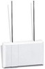
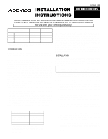
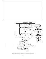
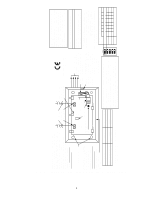
N7635V3 4/98 INSTALLATION INSTRUCTIONS RF RECEIVERS 4281 Series 5881 Series 5882 Series UNLESS OTHERWISE NOTED, ALL INFORMATION CONTAINED IN THESE INSTALLATION INSTRUCTIONS APPLIES TO BOTH THE 4281 AND 5881 SERIES OF RF RECEIVERS, AND TO THEIR CANADIAN VERSIONS For use with QED control panels only! 4281 Series 5881 Series 5882 Series (Canada) 4281L 4281CN-L (Canada) 5881L 5882L 4281M 4281CN-M (Canada) 5881M 5882M 4281H 4281CN-H (Canada) 5881H 5882H 5881EH* - * The 5881EH is an enhanced version of 5881H. See bulleted paragraph in INTRODUCTION section. INTRODUCTION The 4281/4281CN and 5881/5882 family of RF receivers are designed for use with QED control panels that support an RF receiver connection via the remote keypad connection points. The receiver recognizes alarm, status and keypad control messages from wireless transmitters operating at 345MHz (in Canada, 315MHz for 4281CN series). For brevity, the various versions of these receivers are referred to herein as "receiver" unless otherwise noted. One or two individually identified receivers can be employed, depending on the control used. Connection of multiple receivers to a QED con trol can provide redundant coverage or extend coverage in large areas. Multiple receivers do not increase the number of transmitters that the system can support. See the QED control's instructions for specific information regarding the number and type of receivers that can be supported. These receivers feature a Spatial Diversity System which virtually elimi nates the possibility of "Nulls" and "Dead Spots" within the coverage area. • The 4281/4281CN family of receivers are used in conjunction with 5700 series transmitters. • The 5881/5882 family of receivers are used in conjunction with QED 5800 series transmitters. • The 5881EH is an enhanced version of the 5881H using Ademco's new SignalSentry™ technology, and is intended for use in commercial fire installations. To comply with commercial fire applications, the 5881EH can only be used with control panels that are approved for use in commercial fire installations. Note: You will find identification of the receiver model on the unit's PC board (see Diagram 2 for location). Each receiver supports the number of zones shown below. 4281L/4281CN-L Up to 4 zones 4281M/4281CN-M Up to 8 zones 4281H/4281CN-H *See below 5881L/5882L Up to 8 zones 5881M/5882M Up to 16 zones 5881H/5881EH/5882H *See below * The number of zones that the 4281H, 5881H/5881EH or 5882H receiver can support depends on the QED control with which it is used. See the QED control panel's instructions for specific details. If a receiver is connected to a system in which more than the permitted number of wireless zones have been programmed, a "SET UP ERROR" message (Alpha keypads) or an "E4 or "E8"" message (fixed-word keypads) will be displayed on the system's keypad, and none of the zones will be protected. The instruction manual that accompanies the QED control includes recommendations regarding receiver and transmitter locations, the types of wireless zones that can be programmed (e.g. ENTRY/EXIT, PERIMETER, INTERIOR, etc.) and the procedure for programming the receivers. These receivers should not be installed in an area subject to environmental extremes of below freezing (such as an unheated warehouse) or extremely high temperatures (such as an attic). INSTALLATION With some QED controls, a receiver may be mounted directly inside the control's cabinet (receiver circuit board only, without its plastic housing) instead of remotely (in its own housing). In both cases, avoid mounting the receiver antennas against a metal surface. Using The 5881EH In Commercial Fire Applications The 5881EH must be mounted in a separate cabinet for commercial fire applications. Refer to step 4. 1. Remove the receiver's cover by inserting and twisting a screwdriver blade in the slot at the center of the cover's lower edge. 2. If the receiver is to be mounted within the control's cabinet (refer to Diagram 1): a. Remove the receiver's circuit board from its base by bending back the two flexible plastic tabs that hold the board's lower edge. b. In the control's cabinet, unfasten and move the control circuit board downward (if already installed). c. Hang two short (black) mounting clips (provided with the receiver) on the raised cabinet tabs in the cabinet, as shown in Detail B of Diagram 1. d. Insert the top of the receiver board into the supporting slots provided at the top of the cabinet, as shown in Detail A. Swing the bottom of the receiver board into the two short (black) mounting clips installed in step c, and secure it to the cabinet with the accompanying screws. See Detail B. e. Insert the top of the control's board into the slot in the black clips holding the lower edge of the receiver board (see Detail B), and position two long (red) clips at the lower edge of the board (see Detail C). f. Swing the lower edge of the control board into place, and secure with two additional screws. g. Insert one of the two grounding lugs (provided with the receiver) through the top of the cabinet and into the left-hand terminal of one of the antenna blocks (at the upper edge of the receiver's circuit board). Secure it to the cabinet with one of the two screws provided. See Detail D.
-
 1
1 -
 2
2 -
 3
3 -
 4
4 -
 5
5 -
 6
6 -
 7
7
 |
 |