Honeywell 5890PI Installation Instructions
Honeywell 5890PI Manual
 |
View all Honeywell 5890PI manuals
Add to My Manuals
Save this manual to your list of manuals |
Honeywell 5890PI manual content summary:
- Honeywell 5890PI | Installation Instructions - Page 1
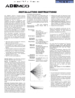
® For use with Q.E.D. control panels only. Previous Menu No. 5890PI PASSIVE INFRARED MOTION DETECTOR/TRANSMITTER INSTALLATION INSTRUCTIONS GENERAL INFORMATION The 5890PI Passive Infrared Motion Detector/Transmitter is a battery-operated wireless device intended for use as part of a 5800 series - Honeywell 5890PI | Installation Instructions - Page 2
For installation with pets, be sure to follow the guidelines described in Table 2. Radio Transmission Path Check Verify that a strong transmission path between the 5890PI and the system's Receiver/Control exists before permanently mounting the detector. Do this by performing the Walk-Test (described - Honeywell 5890PI | Installation Instructions - Page 3
be readjusted. 4. Walk-Tests should be conducted frequently (at least weekly) to confirm continued proper coverage. TABLE 1. INSTALLATION GUIDE FOR MOUNTING HEIGHTS Lens Part No. 5890PI (Standard as installed) Description/ Coverage Pulse Count PIR Mounting Height PET IMMUNE LENS Req'd for 35 - Honeywell 5890PI | Installation Instructions - Page 4
to compromise or failure to warn for a variety of reasons: • Passive Infrared Motion Detectors can detect intrusion only within the designed ranges as diagrammed in this installation manual. • Passive Infrared Motion Detectors do not provide volumetric area protection. They do create multiple beams
-
 1
1 -
 2
2 -
 3
3 -
 4
4
 |
 |
1
N5987-1
3/98
®
No. 5890PI
PASSIVE INFRARED MOTION
DETECTOR/TRANSMITTER
INSTALLATION INSTRUCTIONS
GENERAL INFORMATION
The 5890PI Passive Infrared Motion
Detector/Transmitter is a battery-operated
wireless device intended for use as part of a
5800 series wireless alarm system.
Designed for use in commercial and
residential installations, the 5890PI is a wall -
mounted unit with a standard lens that
provides wide-angle protection up to a range
of 35 ft (10.6m). For best coverage, mount the
detector so that the likely direction of
intruder motion is
across
the pattern.
When installed per the guidelines, the Split -
Zone Optics technology in the 5890PI
provides reasonable false alarm protection
against pets and other animals up to 40 lbs.
This
document
provides
installation
instructions for the 5890PI, but the installer
must be familiar with the installation
instructions for the 5800 Wireless Alarm
System with which the 5890PI is intended to
be used.
FEATURES
•
Split-Zone Optics provides pet immunity
against animals up to 40 lbs.
•
Wireless operation for fast installation.
•
Dual-element pyro-electric sensor provides
positive protection while minimizing false
alarms.
•
Alternate polarity pulse count option offers
greater stability in adverse environments.
•
Provision to turn LED on while Walk-
Testing (LED is turned off after testing).
•
Tamper-protected cover – unit transmits
message if cover is removed.
•
Wall or corner mounting options.
SYSTEM DESCRIPTION
Optical System:
Uses efficiently designed
Fresnel lenses with Split-Zone Optics.
Radio
Transmitter:
The
built-in
transmitter serves only as the communication
link to the alarm system's Receiver/Control,
and can send alarm, tamper, supervisory, and
battery status messages to the system's
receiver/control. The transmitter is not used
for detection purposes. Each detector has a
unique ID code permanently assigned at the
factory. You must enroll this ID into the
control system at the time of installation.
This allows each detector used in the system
to be uniquely identified. You must program
the control to enroll the 5890PI as an "RF"
type unit (i.e., supervised RF).
To conserve battery life during normal
operation, no more than one transmission
sequence will occur within a 3-minute period.
There is no such time restriction in "Test"
mode.
Alternate Polarity Pulse Count:
Two
jumper-selectable detection response modes
are provided:
Instant response
(Pulse Count
OFF) and
Alternate Polarity Pulse Count
(Pulse Count ON). With Pulse Count OFF,
any detected change in infrared energy will
trigger an immediate alarm signal. This mode
is recommended when the detector is used to
monitor a narrow hallway where coverage is
provided by only a single zone.
Use the Pulse Count ON mode when the
detector is installed in areas where periodic
changes in infrared energy levels are normal
(for example, where forced-air heating ducts
are present). In this mode, at least two
changes in infrared energy must be detected
within a short period before an alarm will be
triggered.
Important
Note:
˚For pet immune
applications, Pulse Count ON is
recommended.
SPECIFICATIONS
Pet Immune
Lens
:
35 ft x 45 ft
(10.6m x 13.7m).
30 zones (8 long, 7 over 7
intermediate, 4 over 4
short range).
Pulse Count:
Installer-selectable
On/Off link.
Detectable
Walk Rate:
0.5 –
10 ft/sec
(0.15 - 1.5m/sec).
Mtg. Height:
7.0 ft recommended (2.1m),
but may be mounted at
other heights (see Table 1).
Walk Test
Indicator:
Red LED with
Test/Normal (disable) link.
Batteries:
Two
3-volt Lithium
batteries.
Use only
Ademco No. 466,
Duracell DL123A,
Panasonic CR123A,
Sanyo CR123A or
Varta CR123A.
0perating
Temperature:
32
°
F – 122
°
F (0
°
C - 50
°
C).
Operating
Humidity:
Up to 95% RH (max.), non-
condensing.
Dimensions:
2-11/16"W x 5"H x 1-7/8"D
68mm x 127mm x 48mm.
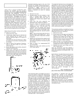
ALTERNATE
COUNT POLARITY
EACH ZONE CONSISTS
OF 2 FIELDS
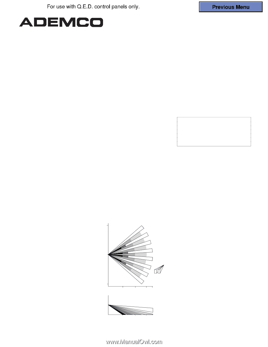
0
25'
(7.6m)
25'
(7.6m)
10'
(3m)
20'
(6m)
30'
(9m)
35'
(10.6m)
0
7.5'
(2.3m)
0
10'
(3m)
20'
(6m)
30'
(9m)
35'
(10.6m)
Figure 1.
Protection Pattern
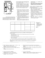
BATTERY INSTALLATION
1.
Remove front cover by inserting a large
screwdriver blade (or small coin) in groove
between cover and base at the location
shown in Figure 2; rotate blade to
override snap fit, then lift cover off.
2.
Observing correct polarity,
install the
two Lithium batteries (supplied
)
into the
battery holders,
as shown in Figure 5.
Make sure the batteries are firmly seated.
3.
Replace the cover (snap fit).
Battery Caution:
Risk of fire, explosion, and burns. Do not
recharge, disassemble, heat above 100
°
C, or
incinerate. Dispose of used batteries
promptly. Keep away from children.
Programming Note:
If you have not
programmed the detector’s ID into the
system (i.e., this is an initial detector
installation), refer to the
PROGRAMMING
section below and perform the ID enrolling
procedure before mounting or testing the
detector.
PROGRAMMING
You must enroll the detector’s ID during
installation of the system.
You should
program the 5890PI as an “RF” type unit
(i.e., supervised RF). and the "Loop"
number as "1".
To program the detector, place the LED
jumper in the TEST position (see Figure 5),
the Pulse Count jumper in the OFF position,
batteries installed and cover on. Temporarily
cover the lens (a cloth will do) to prevent any
activation by the detector.
With the control in Zone Programming mode,
at the "Input serial number" prompt, remove
the cloth cover and motion your hand over the
lens to activate the detector and cause it to
send a FAULT; then cover the lens again to
send a RESTORE. Repeat this procedure to
confirm the serial number enrolled.
Alternatively, you can enter the serial
number manually.
Return LED jumper to the NORMAL
position.
See the control unit’s installation instructions
for further details.
INSTALLATION HINTS
•
Do not install where the detector is exposed
to direct sunlight or directly above strong
sources of heat.
•
Make sure the detection area does not have
obstructions (curtains, screens, large pieces
of furniture, plants, etc.) which may block
the pattern of coverage.
•
Avoid locating a unit in areas which
contain objects likely to produce a rapid
change in temperature, such as central
heating, radiators, or ducts (or heaters of
any kind), air conditioners, open flame, etc.
•
Do not mount on an unstable surface.