Honeywell 5890PI Installation Instructions - Page 3
Table 1., Installation Guide For Mounting Heights - low battery
 |
View all Honeywell 5890PI manuals
Add to My Manuals
Save this manual to your list of manuals |
Page 3 highlights
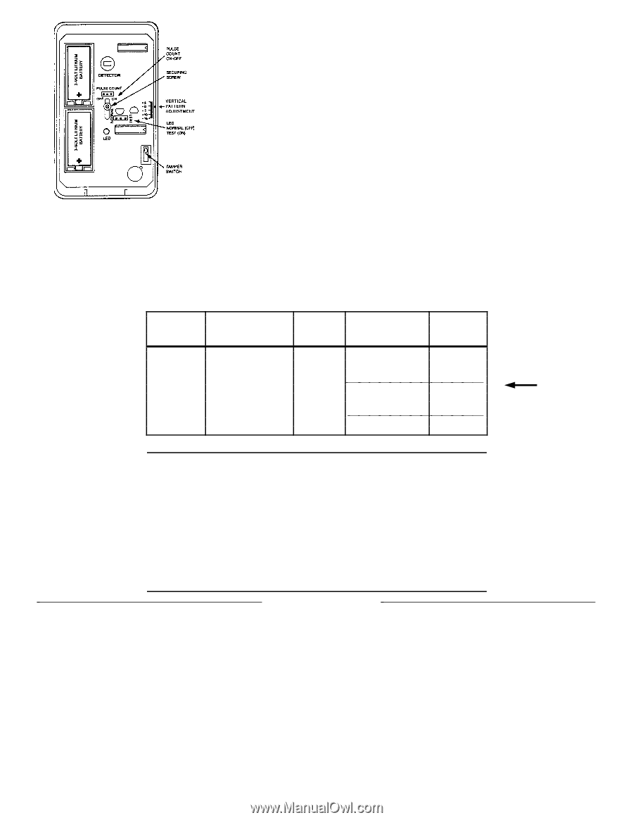
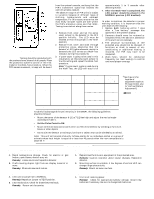
Figure 5. PC Board TEST PROCEDURES Important: Testing should be conducted with the protected area cleared of all people. Place the protective system's control in the Test mode for the Walk-Test procedure. When the PIR senses movement, a beep will be heard from the system's console, verifying that the PIR's transmitter signal has reached the control's wireless receiver. The absolute range of all PIR units is subject to variation because of different types of clothing, backgrounds and ambient temperature. For this reason, ensure that the most likely intruder routes are well within the PIR's protective zones and that Walk Testing is carried out along these routes. Walk-Test 1. Remove front cover and set the pulse count jumper in the detector in the OFF position initially. The LED must be enabled at this time (jumper in the TEST position). 2. Replace front cover and walk through protective zones, observing that the detector's LED lights whenever motion is detected (the LED serves as a Walk-Test indicator during this procedure). 3. If pulse count is going to be used in this installation, set the pulse count jumper to the ON setting and repeat the Walk-Test procedure. Note: If pulse count mode is used during the Walk-Test, the LED will stay lit for approximately 1 to 3 seconds after detecting motion. 4. After the Walk-Test is completed, the LED jumper should be placed in the NORMAL position (LED disabled). MAINTAINING PROPER OPERATION In order to maintain the detector in proper working condition, it is important that the user observes the following: 1. Replace both batteries within 7 days after a "low battery" message has appeared in the system's display. 2. Detectors should never be re-aimed or relocated without the advice or assistance of the alarm service company. 3. The physical surroundings of the protected area should not be changed. If furniture or stock is moved, or airconditioning or additional heating is installed, the PIR may have to be readjusted. 4. Walk-Tests should be conducted frequently (at least weekly) to confirm continued proper coverage. TABLE 1. INSTALLATION GUIDE FOR MOUNTING HEIGHTS Lens Part No. 5890PI (Standard as installed) Description/ Coverage Pulse Count PIR Mounting Height PET IMMUNE LENS Req'd for 35 ft x 45 ft installations (10.6m x 13.7m) with pets 6.5 ft (2.0m) 7 ft (2.1m) Pattern Setting (Deg) +2° +1° † See Figure 5 for location of adjustment scale on PC board (refer also to "Vertical Pattern Adjustment") OPTIMUM PET IMMUNITY . 7.5 ft (2.3m) +1° TABLE 2. SPECIAL INSTRUCTIONS FOR INSTALLATION WITH PETS To take full advantage of the pet immunity in the 5890PI, the following guidelines should be followed: • Mount the center of the detector 6-1/2 to 7-1/2 feet high and adjust the vertical angle according to Table 1. • Set the Pulse Count to ON. • Mount where animals cannot come within six feet of the detector by climbing on furniture, boxes, or other objects. • Do not aim the detector at stairways, furniture or objects that can be climbed by an animal. Note: This unit will provide immunity to false alarms for an individual animal or a group of animals whose total weight is equal to or less than 40 pounds when the room temperature is above 50° F. TROUBLESHOOTI NG Trouble 1: INTERMITTENT ALARM Probable Causes: A. Rapid temperature change. Check for electric or gas heaters, open flames, electric arcs, etc. Remedy: Locate source and reposition detector. B. Drafts causing drapes, light fixtures, display material to move. Remedy: Eliminate source of motion. Trouble 2: LED INOPERATIVE DURING WALK-TEST Probable Causes: A. LED control jumper set to NORMAL. Remedy: Reposition jumper to TEST position. B. LED malfunction. Check for broken/shorted leads. Remedy: Return unit for service. Trouble 3: DETECTION AREA CHANGES Probable Causes: A. Repositioned furniture or equipment in the protected area. Remedy: Caution customer about layout changes. Reposition detector. B. Mounting surface is unstable. A few degrees of vertical shift can change range substantially. Remedy: Mount on secure surface. Trouble 4: UNIT DOES NOT APPEAR TO BE OPERATING Probable Cause: A. Unit is not receiving power. Remedy: Check for appropriate battery voltage. Install new batteries if necessary. Be sure to change both batteries. 3
-
 1
1 -
 2
2 -
 3
3 -
 4
4
 |
 |