Honeywell CT1500 Owner's Manual - Page 9
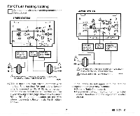
CT1501 heating/cooling
 |
View all Honeywell CT1500 manuals
Add to My Manuals
Save this manual to your list of manuals |
Page 9 highlights
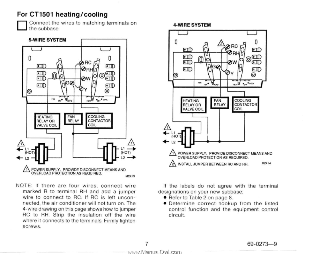
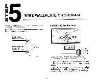
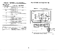
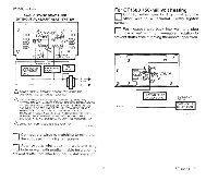
For CT1501 heating/cooling Connect the wires to matching terminals on the subbase. 5-WIRE SYSTEM I 4-WIRE SYSTEM U U I I RELAY OR VALVE COIL I I CONTACTOR I I I 1 POWER SUPPLY. PROVIDE DISCONNECT MEANS AND M2&13 NOTE: If there are four wires, connect wire marked R to terminal RH and add a jumper wire to connect to RC. If RC is left unconnected, the air conditioner will not turn on. The 4-wire drawing on this page shows how to jumper RC to RH. Strip the insulation off the wire where if connects to the terminals. Firmly tighten screws. A POWER SUPPLY. PROVIDE DISCONNECT MEANSAND A OVERLOAD PROTECTIONAS REOUIRED. INSTALLJUMPER BETWEEN RC AND RH. Ma" If the labels do not agree with the terminal designations on your new subbase Refer to Table 2 on page 8 Determine correct hookup from the listed control function and the equipment control circuit 7 69-0273-9 ~ ~
-
 1
1 -
2
-
3
-
 4
4 -
 5
5 -
 6
6 -
 7
7 -
 8
8 -
 9
9 -
 10
10 -
 11
11 -
 12
12 -
 13
13 -
 14
14 -
15
-
16
-
17
-
18
-
19
-
20
 |
 |