Honeywell CT1800 Owner's Manual
Honeywell CT1800 Manual
 |
View all Honeywell CT1800 manuals
Add to My Manuals
Save this manual to your list of manuals |
Honeywell CT1800 manual content summary:
- Honeywell CT1800 | Owner's Manual - Page 1
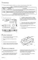
local waste management authority for instructions regarding recycling and the proper disposal of this control, or of an old control containing mercury in a sealed tube. THERMOSTAT FEATURES I-Front of thermostat. LOW TEMPERATURE CONTROL LEVER (BLUE) HIGH TEMPERATURE CONTROL LEVER (RED) II-Hinged - Honeywell CT1800 | Owner's Manual - Page 2
THERMOSTAT AND SUBBASE APPLICATIONS.a Thermostat Subbase Wallplate Model Included For Use With CT1800 199986B Wallplate 2- or 3- wire, 150 to 30 volt control Step 4). To order check your telephone directory for your local Honeywell distributor. Test to make certain that your heating and cooling - Honeywell CT1800 | Owner's Manual - Page 3
on a system with B or O terminals. One or two extra wires? If you are replacing a Honeywell Chronotherm® Thermostat, you may find one or two wires that go to the clock terminals on the Chrontherm® Thermostat wiring wallplate. Do not allow them to touch, or you may damage your transformer. Disconnect - Honeywell CT1800 | Owner's Manual - Page 4
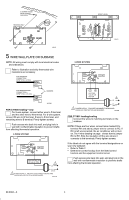
CONNECTION- STRIP 7/16 in. [11 mm] BARRIER M1556B FOR CT1800 heating-only For 2-wire system, connect either wire to R insulation to prevent drafts from affecting thermostat operation. 2-WIRE SYSTEM R W hookup from the listed control function and the equipment control circuit. Push excess wire - Honeywell CT1800 | Owner's Manual - Page 5
WIRE TO "Y" AND ONE TO "W", USE "Y" AND "W" ON NEW THERMOSTAT; DO NOT USE "P". IMPORTANT- IF OLD THERMOSTAT USES A W2 (AUXILIARY OR EMERGENCY HEAT) TERMINAL, THIS THERMOSTAT MAY NOT BE USED. THIS THERMOSTAT IS NOT DESIGNED TO CONTROL AUXILIARY HEAT. 3 SOME HEAT PUMPS USE "B" INSTEAD OF "O". M2415B - Honeywell CT1800 | Owner's Manual - Page 6
information can be found printed on the primary control at the furnace or boiler. The primary control is usually a gas valve, a relay or burner control box, Aquastat controller or zone valve with the thermostat wires connected to it. These controls are usually located behind the furnace cover - Honeywell CT1800 | Owner's Manual - Page 7
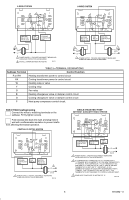
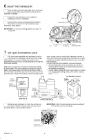
it engages catch at bottom of base. M9618 11 CHECKOUTTHERMOSTAT OPERATION AND SETTEMPERATURE CONTROL LEVERS The two levers on top of the thermostat control the low and high temperature for energy savings and comfort control as shown in the illustration. LOW TEMPERATURE (BLUE MARK) SET LEVER HIGH - Honeywell CT1800 | Owner's Manual - Page 8
. The heat should shut off. Operate the entire heating system for at least one complete cycle. IMPORTANT: If thermostat fails any test, refer to the Troubleshooting Guide in Owner's manual. Heating/Cooling System Turn on power to the furnace and cooling system. Place the system switch lever at HEAT
-
 1
1 -
 2
2 -
 3
3 -
 4
4 -
 5
5 -
 6
6 -
 7
7 -
8
 |
 |
D.F. •
Rev. 11-96
•
Printed in U.S.A.
•
•
©Honeywell Inc. 1996
•
Form Number 69-0394—3
Installation Instructions
CT1800 24V gas or oil heat, or 3 wire zone valves.
CT1801 24V gas or oil heat/cool.
CT1802 24V central electric heat/cool or single stage
heat pump without auxiliary heat.
Not for use on line voltage (120V) millivolt systems
.
CT1800, CT1801, CT1802
Electromechanical Fuel Saver Thermostat and Wallplate/Subbase
Recycling Notice
This control contains mercury in a sealed tube. Do
not
place control in the trash at the end of its useful life.
If this control is replacing a control that contains mercury in
a sealed tube, do
not
place your old control in the trash.
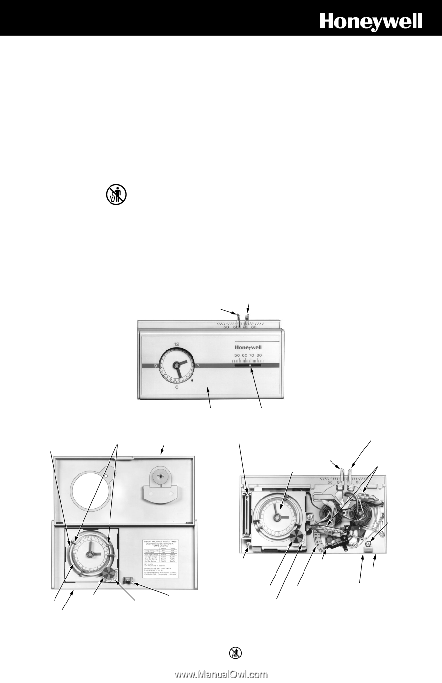
THERMOSTAT FEATURES
I—Front of thermostat.
M9613
HIGH TEMPERATURE
CONTROL LEVER
(RED)
LOW TEMPERATURE
CONTROL LEVER (BLUE)
THERMOSTAT COVER
THERMOMETER
THERMOSTAT
BASE
24 HOUR PROGRAM DIAL
(GRAY AREA FOR
NIGHT SETTINGS)
AAA ALKALINE
BATTERY (2) INCLUDED
LOW TEMPERATURE
CONTROL LEVER
(BLUE)
HIGH
TEMPERATURE
CONTROL LEVER
(RED)
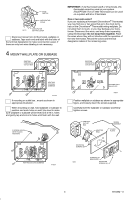
SWITCH
BULBS
CAPTIVE
MOUNTING
SCREW
CAPTIVE
MOUNTING
SCREW
WALLPLATE (BEHIND
THERMOSTAT. HELD
ON BY TWO CAPTIVE
SCREWS.)
ADJUSTABLE HEAT
ANTICIPATOR
PROGRAM
INDEX WHEEL
TIME INDICATOR
ARROW
HEAT
ANTICIPATOR
SETTING
LEVER
M9615
III—Cover removed.
II—Hinged cover lifted.
24 HOUR PROGRAM DIAL
(GRAY AREA FOR NIGHT
SETTING)
TIME
INDICATOR
ARROW
PROGRAM
PIN
STORAGE
THERMOSTAT COVER
PROGRAM
INDEX WHEEL
PROGRAM
PIN SLOT
PROGRAM PINS
FLIP-UP
COVER
M9614
Contact your local waste management authority for
instructions regarding recycling and the proper disposal of
this control, or of an old control containing mercury in a
sealed tube.