Honeywell CT3550 Owner's Manual
Honeywell CT3550 Manual
 |
View all Honeywell CT3550 manuals
Add to My Manuals
Save this manual to your list of manuals |
Honeywell CT3550 manual content summary:
- Honeywell CT3550 | Owner's Manual - Page 1
Weekday, Saturday and Sunday Programmable Heat and/or Cool Low Voltage (20 to 30 Vac) Thermostat and Wallplate Model CT3550 Honeywell CT3550 PROGRAMMABLE THERMOSTAT OWNER'S GUIDE Para pedir estas instrucciones en español, llame al 1-800-468-1502. Pour obtenir ce ode demploi en français, composer - Honeywell CT3550 | Owner's Manual - Page 2
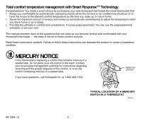
, or set your own. This manual answers many of the questions that can arise as you become familiar and comfortable with your Honeywell thermostat - the state of the art in home comfort controls. Read these instructions carefully. Failure to follow these instructions can damage the product or cause - Honeywell CT3550 | Owner's Manual - Page 3
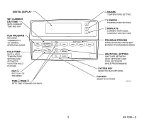
DIGITAL DISPLAY SET CURRENT DAY/TIME SETS CURRENT TIME AND DAY RUN PROGRAM RETURNS THERMOSTAT TO NORMAL OPERATING MODE Run Program Set Current Day/Time Time Wake Set Program Leave Return Sleep HOLD TEMP SETS A HOLD TEMPERATURE SETTING AND ACTIVATES - Honeywell CT3550 | Owner's Manual - Page 4
IS "CALLING" FOR HEAT OR COOL DISPLAYS EITHER ROOM OR SET TEMPERATURES SHOWS CURRENT FAN KEY POSITION ON/AUTO SHOWS THERMOSTAT IS CALLING FOR THE FAN SHOWS THERMOSTAT IS PROCESSING INFORMATION AND WAITING TO CALL FOR HEAT OR COOL SHOWS SMART RESPONSE IS OFF. CONVENTIONAL RECOVERY IS ON SHOWS - Honeywell CT3550 | Owner's Manual - Page 5
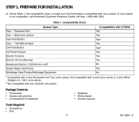
Honeywell and Taco zone valves. Not compatible with 3-wire zone valves or 2-wire White Rodgers no. 1361 zone valves. b Not compatible with any 120/240 volt system. Package Contents. • Thermostat • Screws and anchors • 3 Energizer® AA batteries • Wallplate • Wiring labels • Owners manual Tools - Honeywell CT3550 | Owner's Manual - Page 6
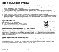
Carefully unpack your new thermostat and wallplate. Save package of screws, instructions, and receipt. ❑ Remove the cover from the old thermostat. If the cover M5136 Replacing a Clock Thermostat that has C or C1 Clock Terminals If you are replacing a Honeywell Chronotherm® Thermostat, you may find - Honeywell CT3550 | Owner's Manual - Page 7
Pull the wires through the wiring opening. Loosely insert mounting screws into each of the holes. ❑ Level the wallplate if desired. Thermostat functions properly when not level. ❑ Tighten mounting screws. WALL WIRES THROUGH WALL M16427 WALL ANCHORS (2) MOUNTING HOLES MOUNTING SCREWS M15044 - Honeywell CT3550 | Owner's Manual - Page 8
Refer to the labels you placed on the wires when you removed the old thermostat (see illustration). ❑ Match the letter of your old thermostat wire with the corresponding terminal letter on your new thermostat. Refer to Table 2. ❑ Remove the factory-installed jumper connecting terminals R and RC if - Honeywell CT3550 | Owner's Manual - Page 9
Y2 Do not continue installation. Second stage heat. Call 1-800-468-1502. Second stage cool. a If both RH and R terminals are present on existing thermostat, remove jumper and connect Rh to R and R to Rc. b Do not connect both O and B when wiring to a single stage heat pump. Connect O to O. Tape - Honeywell CT3550 | Owner's Manual - Page 10
80 90 batteries do not last as long. They also can leak, causing damage to the thermostat and the wall surface. Honeywell recommends Energizer® batteries. STEP 6. MOUNT THE THERMOSTAT A. ENGAGE TABS AT TOP OF THERMOSTAT AND WALLPLATE. B. PRESS LOWER EDGE OF CASE TO LATCH. 69-1284-2 10 M12703 - Honeywell CT3550 | Owner's Manual - Page 11
STEP 7. CUSTOMIZE YOUR THERMOSTAT Your Honeywell CT3550 thermostat comes preset to the most commonly used settings. or oil furnace. Furnace controls fan operation during heating (preset). NUMBER - 1 = Electric furnace or single stage heat pump. Thermostat controls fan operation during heating. - Honeywell CT3550 | Owner's Manual - Page 12
To change your system type: ❑ Press until display shows your furnace or boiler type. ❑ Press Time Run to move to next feature or Program to return to main display. Smart Response™ Technology (Feature Number 13) Smart Response technology options are: - 0 = Smart Response technology on (preset). - - Honeywell CT3550 | Owner's Manual - Page 13
. (Tapping the Day/Time will advance the time in one hour ❑ Press Run . Program STEP 9. PROGRAMMING The keyboard is located behind the thermostat cover. The three most frequently used keys are near the display. Pressing displays the current temperature settings. Pressing the and keys change the - Honeywell CT3550 | Owner's Manual - Page 14
Table 3 can be helpful when planning your schedule of time and temperature settings. The thermostat default settings are shown in parentheses ( ). Table 3. Personal Programming Table. Period Wake Leave Return Sleep Default Setting Time (6:00AM) Heata (70°F/21°C) Coolb (78°F/25.5°C) - Honeywell CT3550 | Owner's Manual - Page 15
❑ Press or until the desired wake temperature displays. The setpoint temperature range is 40°F to 90°F (4.5°C to 32°C) for heating and 45°F to 99°F (7°C to 37°C) for cooling. ❑ Press Heat/Cool Settings to switch between setpoints. NOTE: Program times are the same for heating and cooling. ❑ - Honeywell CT3550 | Owner's Manual - Page 16
STEP 10. OPERATING YOUR THERMOSTAT Change Temperature Setting Until the Next Program Period (Temporary Change) ❑ Press or until the screen shows the desired temperature setting. NOTE: The temporary temperature setting - Honeywell CT3550 | Owner's Manual - Page 17
during normal operation, the fan reverts to the programmed fan setting when the next program period begins. Set the System Key Heat: The thermostat controls your heating system. Press System until display shows Heat. Off: Both the heating and air conditioning systems are off. Press System until the - Honeywell CT3550 | Owner's Manual - Page 18
If You Have a Problem Table 4. Solution Guide. If... Then... Display does not appear. • Make sure the batteries are installed correctly. • Make sure the thermostat is mounted and latched on the wallplate. Mount and latch the thermostat on the wallplate if it is not. Temperature settings will - Honeywell CT3550 | Owner's Manual - Page 19
for Smart Response control, the start times occur before your programmed comfort periods. Toll-Free Customer Assistance Please read and follow the provided instructions for this thermostat. For additional information, go to www.honeywell.com/yourhome or call the Honeywell Customer Relations Center - Honeywell CT3550 | Owner's Manual - Page 20
The time of day when you want the comfort temperature established. When the thermostat activates Smart Response technology, the thermostat displays In Recovery, changes the setpoint, and turns on the system. • Your CT3550 thermostat learns from experience. Each day it checks how closely it hit the - Honeywell CT3550 | Owner's Manual - Page 21
COIL 1 1 POWER SUPPLY. PROVIDE DISCONNECT MEANS AND OVERLOAD PROTECTION AS REQUIRED. M10616 3-WIRE HEAT ONLY WITH FAN (JUMPER INTACT) THERMOSTAT B RC O W Y R G HEATING RELAY OR VALVE COIL FAN RELAY 1 POWER SUPPLY. PROVIDE DISCONNECT MEANS AND OVERLOAD PROTECTION AS REQUIRED. 1 M10618 - Honeywell CT3550 | Owner's Manual - Page 22
DAMPER HEAT RELAY COMPRESSOR CONTACTOR COOL DAMPER 1 POWER SUPPLY. PROVIDE DISCONNECT MEANS AND OVERLOAD PROTECTION AS REQUIRED. FAN RELAY 1 M18738 Notice: This thermostat is a Class B digital apparatus that complies with Canadian Radio Interference Regulations, CRC c. 1374. 69-1284-2 22 - Honeywell CT3550 | Owner's Manual - Page 23
or materials, under normal use and service, for a period of one (1) year from the date of purchase by the consumer. If, at any time during the warranty period, the product is defective or malfunctions, Honeywell shall repair or replace it (at Honeywells option) within a reasonable period of time - Honeywell CT3550 | Owner's Manual - Page 24
Home and Building Control Honeywell 1985 Douglas Drive North Golden Valley, MN 55422 Home and Building Control Honeywell Limited-Honeywell Limitée 35 Dynamic Drive Scarborough, Ontario M1V 4Z9 69-1284-2 J.H. Rev. 04-01 Printed in U.S.A. on recycled paper containing at least 10% post-consumer
-
 1
1 -
 2
2 -
 3
3 -
 4
4 -
 5
5 -
 6
6 -
 7
7 -
8
-
9
-
10
-
11
-
12
-
13
-
14
-
15
-
16
-
17
-
18
-
19
-
20
-
21
-
22
-
23
-
24
 |
 |
Place Bar Code Here
69-1284-2
OWNER’S GUIDE
® U.S. Registered Trademark
Copyright © 2001 Honeywell •
•All Rights Reserved
Honeywell CT3550
PROGRAMMABLE THERMOSTAT
Weekday, Saturday and Sunday
Programmable Heat and/or Cool
Low Voltage (20 to 30 Vac) Thermostat and Wallplate
Model CT3550
Para pedir estas instrucciones en español, llame al 1-800-468-1502.
Pour obtenir ce ode demploi en français, composer le 1-800-468-1502.
Table of Contents
Step 1. Prepare for Installation
..................................................................................................................................
5
Step 2. Remove Old Thermostat
...............................................................................................................................
6
Step 3. Mount Thermostat Wallplate
.........................................................................................................................
7
Step 4. Wire Wallplate Terminals
...............................................................................................................................
8
Step 5. Install the Batteries
.......................................................................................................................................
9
Step 6. Mount the Thermostat
...................................................................................................................................
10
Step 7. Customize Your Thermostat
..........................................................................................................................
11
Step 8. Set the Clock
.................................................................................................................................................
13
Step 9. Programming
................................................................................................................................................
13
Step 10. Operating Your Thermostat
.........................................................................................................................
16
Step 11. Set the Fan and System Key
......................................................................................................................
17
Smart Response™ Technology
.................................................................................................................................
20
Wiring Diagrams
........................................................................................................................................................
21