Honeywell CT40A Owner's Manual
Honeywell CT40A Manual
 |
View all Honeywell CT40A manuals
Add to My Manuals
Save this manual to your list of manuals |
Honeywell CT40A manual content summary:
- Honeywell CT40A | Owner's Manual - Page 1
To correctly install your Honeywell thermostat, follow these step-by-step instructions. It is recommended that as you read, understand and complete each step, you check it off. If you are unsure about wiring procedures, be sure to call a qualified service technician for assistance. ❑ Check - Honeywell CT40A | Owner's Manual - Page 2
.8 .8 .3 .3 CT40A HEATING THERMOSTAT ADJUSTABLE HEAT ANTICIPATOR INDICATOR MOUNTING HOLE (THERMOSTAT TO WALL OR OUTLET BOX) .1 .4 .6 MOUNTING POSTS (4) (FOR COVER) ADJUSTABLE HEAT ANTICIPATOR SCALE SNAP SWITCH CONTACTS MOUNTING CLIPS (2) (FOR COVER) MOUNTING HOLE (THERMOSTAT TO WALL OR - Honeywell CT40A | Owner's Manual - Page 3
❑ Move the temperature setting lever to the required temperature comfort level. CT40A HEATING THERMOSTAT 7 Troubleshoot Thermostat Your Honeywell thermostat requires minimal attention. Most problems can be corrected as described in Table 2. Symptom No heat. Furnace turns on and off. Major - Honeywell CT40A | Owner's Manual - Page 4
CT40A HEATING THERMOSTAT LIMITED ONE-YEAR WARRANTY Honeywell warrants this product to be free from defects in the workmanship or materials, under normal use and service, for a period of one (1) year from the date of purchase by the consumer. If, at any time during the warranty period, the product is - Honeywell CT40A | Owner's Manual - Page 5
CT40A Thermostat pour chauffage INSTRUCTIONS D'INSTALLATION 1 Préparation Votre nouveau thermostat sera bien installé si vous Caractéristiques du thermostat ❑ Consulter la Fig. 2 pour voir les différentes parties du thermostat. ® Marque déposée aux É.-U. Copyright © 2002 Honeywell • • Tous droits - Honeywell CT40A | Owner's Manual - Page 6
CT40A THERMOSTAT POUR CHAUFFAGE RÉGLAGE DE LA RÉSISTANCE ANTICIPATRICE DE CHALEUR TROU DE MONTAGE (POUR L'INSTALLATION DU THERMOSTAT AU MUR OU SUR LA BOÎTE DE SORTIE) .3 .1 .4 .6 .8 SUPPORTS DE MONTAGE (4) (POUR LE COUVERCLE) ÉCHELLE DE LA RÉSISTANCE ANTICIPATRICE DE CHALEUR CONTACTS À - Honeywell CT40A | Owner's Manual - Page 7
température ambiante. Le système de chauffage devrait arrêter de fonctionner. 6 Réglage du thermostat ❑ Placer le réglage du point de consigne au niveau de confort désiré. 7 Dépannage Le thermostat Honeywell exige peu ou pas d'attention. La plupart des problèmes sont décrits au Tableau 2. . Table - Honeywell CT40A | Owner's Manual - Page 8
CT40A THERMOSTAT POUR CHAUFFAGE GARANTIE LIMITÉE D'UN AN Honeywell garantit ce produit contre tout vice défectuosité ou de mauvais fonctionnement pendant la période de garantie, Honeywell remplacera ou réparera le produit (au gré de Honeywell) dans un délai raisonnable. Si le produit est défectueux,
-
 1
1 -
 2
2 -
 3
3 -
 4
4 -
 5
5 -
 6
6 -
 7
7 -
8
 |
 |

fi U.S. Registered Trademark
Copyright ' 2002 Honeywell °
° All Rights Reserved
INSTALLATION INSTRUCTIONS
69-0847B-1
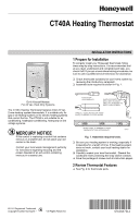
CT40A Heating Thermostat
Do-It Yourself Models
For 24 Vac, Heat-Only Systems
The CT40A Heating Thermostat replaces most 24 Vac,
2-wire heating system thermostats. It is suitable only for
gas or oil heating systems or for electric heating systems
that control the fan. The CT40A is
not suitable
for air
conditioning, heating/air conditioning, heat pump or line
voltage systems.
MERCURY NOTICE
If this control is replacing a control that contains
mercury in a sealed tube, do not place your old
control in the trash.
Contact your local waste management authority
for instructions regarding recycling and the
proper disposal of an old control containing
mercury in a sealed tube.
1 Prepare for Installation
To correctly install your Honeywell thermostat, follow
these step-by-step instructions. It is recommended that
as you read, understand and complete each step, you
check it off. If you are unsure about wiring procedures, be
sure to call a qualified service technician for assistance.
❑
Check thermostat suitability for your home system by
reviewing the introductory paragraph.
❑
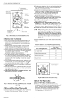
Assemble tools required as shown in Fig. 1.
Fig. 1. Assemble required tools.
❑
Be sure your heating system is working, especially if
inoperative for a length of time. If the heating system
does not work, contact your local heating dealer for
assistance.
❑
Carefully unpack your new thermostat.
Discard the
cardboard insert protecting the snap switch contacts.
❑
Save the package of screws and all instruction pages.
2 Review Thermostat Features
❑
See Fig. 2 for thermostat parts.
FLAT BLADE
SCREWDRIVER
HAND OR POWER
DRILL WITH 3/16 INCH
DRILL BIT, IF NEEDED TO
DRILL HOLES IN WALL
WIRE CUTTER/STRIPPER OR SHARP
KNIFE, IF NEEDED TO STRIP WIRES
SPIRIT LEVEL, IF NEEDED TO LEVEL
THERMOSTAT FOR APPEARANCE
M7337