Honeywell CT62B Owner's Manual - Page 2
Wire And Mount New Thermostat, Check Out Thermostat, Setting Thermostat - electric heat thermostat
 |
View all Honeywell CT62B manuals
Add to My Manuals
Save this manual to your list of manuals |
Page 2 highlights
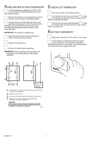
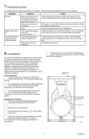
4 WIRE AND MOUNT NEW THERMOSTAT Turn the temperature setting knob to 65°F (18°C). This will prevent accidental damage to the knob stop during mounting. Remove thermostat cover by grasping the top and bottom ends with fingers, and pulling outward. Connect wires to the thermostat as shown in the applicable wiring diagram. Push the wires into the outlet box, and insert the thermostat into the box for mounting by pushing against top and bottom of the thermostat base. IMPORTANT: Do not press on setting knob. Secure the thermostat to the box with the two captive mounting screws provided. Replace thermostat cover. Set knob to desired room temperature. IMPORTANT: Rough handling or strong pressure can damage knob or sensing element, and change calibration. 1 CT62B 3 L2 2 L1 4 CT62A L1 (HOT) L2 1 L1 4 55 60 80 85 5 CHECK OUT THERMOSTAT Turn on the power to the heating system. Turn setting knob all the way clockwise ; listen for clicking sound as switch makes contact. Electric heater should begin operation. Turn knob all the way counterclockwise ; listen for clicking sound as switch breaks contact. Electric heater should shut off. 6 SETTING THERMOSTAT Begin with setting knob at 70°F (20°C) on the scale. If this setting is not satisfactory after at least two hours of operation, turn setting knob upscale to raise the temperature, or downscale to lower the temperature. Move knob only a degree each time. o F 65 70 75 T2 T1 T1 3 TO ELECTRIC HEATER ELECTRIC HEATER 1 POWER SUPPLY. PROVIDE DISCONNECT MEANS AND OVERLOAD PROTECTION AS REQUIRED. 2 BREAKS ON POSITIVE OFF. 3 EXPOSED UNUSED LEADWIRES TO BE PROPERLY INSULATED. 4 THERMALLY ACTIVATED-BREAKS ON TEMPERATURE RISE. MAKES ON TEMPERATURE FALL. CAUTION: SPECIAL SERVICE CO/ALR SOLDERLESS CONNECTORS MUST BE USED WHEN CONNECTING WITH ALUMINUM CONDUCTORS; OTHERWISE, A FIRE HAZARD CAN RESULT. M8420 M8422 69-0829-1 2
-
 1
1 -
 2
2 -
 3
3 -
 4
4
 |
 |