Honeywell CT8602C Owner's Manual - Page 1
Honeywell CT8602C Manual
 |
View all Honeywell CT8602C manuals
Add to My Manuals
Save this manual to your list of manuals |
Page 1 highlights
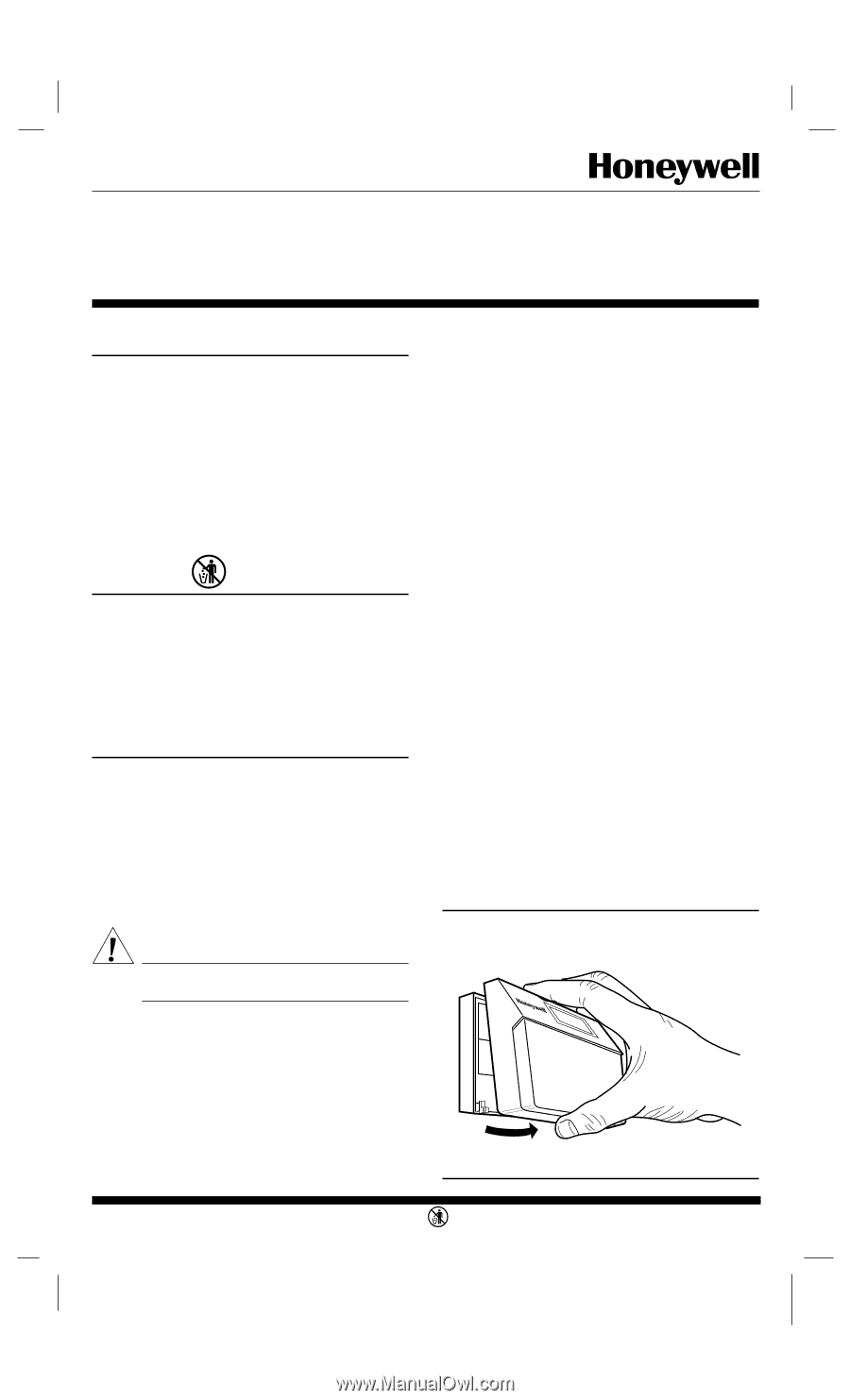
CT8602C Professional Fuel Saver Thermostat Application This thermostat provides energy saving control for a 24 Vac gas, oil, or electric heating or heating/cooling system with independently controlled fan. System switch positions include HEAT-OFF-COOL: fan switch positions include ON-AUTO. Power is supplied for the device by three AA alkaline batteries (included in package). This allows the thermostat to be compatible with all control applications. Heat and cool anticipation is fixed; no adjustment is necessary. Cycle rates are adjustable for heating. The current rating is 1.6A maximum up to 30 Vac. Recycling Notice M3375 If this control is replacing a control that contains mercury in a sealed tube, do not place your old control in the trash. Contact your local waste management authority for instructions regarding recycling and the proper disposal of your old control. If you have any questions, call Honeywell Inc. at 1-800468-1502. Installation WHEN INSTALLING THIS PRODUCT... 1. Read these instructions carefully. Failure to follow them could damage the product or cause a hazardous condition. 2. Check the ratings given on the product to make sure the product is suitable for your application. 3. After installation is complete, check out product operation as provided in these instructions. 4. Allow thermostat to warm to room temperature before operating. CAUTION Disconnect power supply to prevent electrical shock or equipment damage. IMPORTANT: Push excess wire back into the hole, and plug the hole with non hardening caulk, putty or insulation to prevent drafts from affecting thermostat operation. LOCATION Install thermostat and wallplate about 5 ft. (1.5m) above the floor in an area with good air circulation at room temperature. Do not install the thermostat where it may be affected by: - drafts or dead spots behind doors, in corners, or under cabinets. - hot or cold air from ducts. - radiant heat from sun or appliances. - concealed pipes and chimneys. - unheated (uncooled) areas such as an outside wall, behind the thermostat. IF REPLACING AN EXISTING THERMOSTAT Turn off power to thermostat at furnace or boiler. A two- transformer system may require turning off two switches or disconnects. Remove any existing wallplate or subbase from wall. To avoid miswiring later, label or write down each wire with the letter or number on the wiring terminal as the wire is removed. IF NEW INSTALLATION Run cable to the hole in the selected wall location, and pull about 3 in. (76 mm) of wire through the opening. Color-coded, 18 gauge thermostat cable with at least one conductor for each wiring terminal is recommended. MOUNTING WALLPLATE Remove thermostat from wallplate (Fig. 1). The wallplate does not require leveling for operation, but only for appearance. The wallplate mounts directly onto the wall with the screws included in the package. Use the wallplate as a template, and with a pencil, mark two mounting screw positions that best fit the application using two of the three mounting holes in the wallplate (Fig. 2). Use 3/16 in. bit to drill holes for anchors. Gently tap anchors into holes until flush with the wall surface. Thread wires through the center opening of the wallplate. Then mount the wallplate using the two screws provided. Gently tighten screws, level top surface of wallplate, and securely tighten the screws. Fig. 1-Removing thermostat from wallplate. M8850 S. M. • Rev. 3-95 •1 • ©Honeywell Inc. 1995 • Form Number6699--00444466--2 M3375
-
 1
1 -
 2
2 -
 3
3 -
 4
4 -
 5
5 -
 6
6
 |
 |