Honeywell CT8775C Owner's Manual
Honeywell CT8775C Manual
 |
View all Honeywell CT8775C manuals
Add to My Manuals
Save this manual to your list of manuals |
Honeywell CT8775C manual content summary:
- Honeywell CT8775C | Owner's Manual - Page 1
CT8775A,C THE DIGITAL ROUND™ NON-PROGRAMMABLE THERMOSTATS CT8775A Heat Only Thermostat (20 to 30 Vac) and CT8775C Heating-Cooling Thermostat (20 to 30 Vac) Para obtener un documento con las instrucciones en español, por favor visite nuestro sitio de web a: www.honeywell.com/yourhome. Pour obtenir - Honeywell CT8775C | Owner's Manual - Page 2
of The Digital RoundTM Thermostat by Honeywell. • Simple manual answers many of the questions that can arise as you become familiar and comfortable with your Honeywell thermostat - the state of the art in home comfort controls. Read these instructions carefully. Failure to follow these instructions - Honeywell CT8775C | Owner's Manual - Page 3
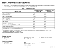
(No. 1311 and 1361). b Not compatible with any 120/240 volt system. Package Contents • Thermostat • Wiring labels Tools for Installation • Screwdriver • Needle nose pliers • Decorator cover plate • Owner's Guide • Drill • Drill bits (3/16 in. drywall, 7/32 in. plaster) 3 • Screws and wall anchors - Honeywell CT8775C | Owner's Manual - Page 4
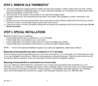
that is connected to six or more wires. • A thermostat that is connected to three wires on a warm air heating only system. • A thermostat that is connected to three wires on a zoned hot water heating system. NOTE: If none of the special installations apply to your particular application, please skip - Honeywell CT8775C | Owner's Manual - Page 5
that is connected to three wires on a warm air heating only system and could turn the fan on by setting the thermostat fan switch to ON, the CT8775C Thermostat will work with your system. Continue with the installation at Step 4. If you purchased a CT8775A thermostat, return the product to the - Honeywell CT8775C | Owner's Manual - Page 6
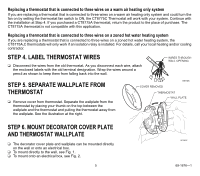
mark the center of the screw holes on the WIRING HOLES left and right sides of the wallplate. Fig. 1. Mount decorator cover plate (optional) and ❑ Remove the wallplate and decorator cover plate (if used) wallplate directly to wall (heating-cooling wallplate and drill two 3/16 in. holes in the - Honeywell CT8775C | Owner's Manual - Page 7
in. screws. ❑ Pull the wires through the wiring hole on the wallplate. ❑ Place the wallplate over the decorator cover plate. Turn the wallplate until the wiring holes are aligned and the two cover plate (required) and wallplate onto electrical box (heating-cooling wallplate shown). 7 69-1676-1 - Honeywell CT8775C | Owner's Manual - Page 8
the corresponding W terminal letter on your new thermostat. Refer to Table 2. IMPORTANT Remove the factory-installed jumper connecting terminals R and Rc on the CT8775C Thermostat if wires will be connected to both of these terminals. ❑ For wiring diagrams, see pp 16-17. ❑ Loosen the terminal - Honeywell CT8775C | Owner's Manual - Page 9
only). Transformer common Do not continue Do not continue Second stage heat. installation. Call 1-800468-1502. installation. Call 1-800468-1502. Second stage cool. NOTES: 1. If wires were connected to both Rh and R terminals on the old thermostat, remove jumper between R and Rc on the new - Honeywell CT8775C | Owner's Manual - Page 10
/Celsius indication, locate DIP switch 1, 2 and 3 on the back of the thermostat. See Fig. 4. Set Heat Cycle Rate ❑ Use DIP switches 1 and 2 to set the heat cycle rate. See Table 3. NOTE: The CT8775A,C Thermostats will provide optimal temperature control if DIP switches 1 and 2 are set according to - Honeywell CT8775C | Owner's Manual - Page 11
Air In Floor Radiant Heat 6 Off Off 9 On Off Check with manufacturer for recommended cycle rate. NOTE: The cooling cycle rate does not require adjustment DIP Switch 3 Off On STEP 9. MOUNT THE THERMOSTAT ENGAGE TABS AT BOTTOM OF THERMOSTAT AND WALL PLATE. PRESS UPPER EDGE OF CASE TO - Honeywell CT8775C | Owner's Manual - Page 12
COOL/OFF/HEAT (CT8775C ONLY) SELECTS ON/AUTO ROOM SET SHOWS THAT THE CURRENT ROOM TEMPERATURE IS DISPLAYED DISPLAYS ROOM OR SET TEMPERATURE SHOWS THAT THE CURRENT TEMPERATURE SETTING IS DISPLAYED DISPLAYS AND ADJUSTS TEMPERATURE SETTING/ TURNS BACKLIGHT ON M19512 Fig. 5. CT8775 Thermostat - Honeywell CT8775C | Owner's Manual - Page 13
AND/OR COOLING SYSTEM Heating System ❑ Slide the system switch to Heat and the Fan switch to Auto (CT8775C only). ❑ Turn the dial clockwise to raise the temperature setting several degrees above the room temperature. ❑ A flame will appear in the display to indicate the thermostat has called for - Honeywell CT8775C | Owner's Manual - Page 14
five minutes before restarting. See equipment manufacturer instructions. ❑ Slide the system switch to Cool and the Fan switch to Auto. ❑ from the display to indicate the thermostat has ended the call for cooling. The cooling system should turn off. Fan (CT8775C Only) ❑ Slide the system switch - Honeywell CT8775C | Owner's Manual - Page 15
com/yourhome or call Honeywell Customer Care, toll free, at 1-800-468-1502. Before calling, please have the following information available: • Thermostat model number. (Located on back of thermostat). • Thermostat date code. (Located below model number). • Type of heating/cooling system (example - Honeywell CT8775C | Owner's Manual - Page 16
Wiring Diagrams R W 1 HEATING RELAY OR VALVE COIL 1 POWER SUPPLY. PROVIDE DISCONNECT MEANS AND OVERLOAD PROTECTION AS REQUIRED. M19450 O B Rc 2 G R Y W 1 HEATING AS REQUIRED. 2 FACTORY INSTALLED JUMPER. M19451 69-1676-1 O B 2 Rc G R Y W 1 HEATING COMPRESSOR FAN RELAY OR - Honeywell CT8775C | Owner's Manual - Page 17
Rc 2 G R Y W COMPRESSOR CONTACTOR HEATING 1 RELAY OR VALVE COIL FAN RELAY 1 1 POWER SUPPLY. PROVIDE DISCONNECT MEANS AND OVERLOAD PROTECTION AS REQUIRED. 2 REMOVE FACTORY INSTALLED JUMPER BETWEEN R AND RC. M19454 Notice: This thermostat is a Class B digital apparatus that complies with - Honeywell CT8775C | Owner's Manual - Page 18
or materials, under normal use and service, for a period of one (1) year from the date of purchase by the consumer. If, at any time during the warranty period, the product is defective or malfunctions, Honeywell shall repair or replace it (at Honeywells option) within a reasonable period of time - Honeywell CT8775C | Owner's Manual - Page 19
19 69-1676-1 - Honeywell CT8775C | Owner's Manual - Page 20
Automation and Control Solutions Honeywell International Inc. Honeywell Limited-Honeywell Limitée 1985 Douglas Drive North 35 Dynamic Drive Golden Valley, MN 55422 Scarborough, Ontario M1V 4Z9 69-1676-1 J.S. Rev. 6-04 www.honeywell.com/yourhome
-
 1
1 -
 2
2 -
 3
3 -
 4
4 -
 5
5 -
 6
6 -
 7
7 -
8
-
9
-
10
-
11
-
12
-
13
-
14
-
15
-
16
-
17
-
18
-
19
-
20
 |
 |

OWNER°S GUIDE
fi U.S. Registered Trademark ° Patents Pending
Copyright ' 2004 Honeywell International Inc.
All Rights Reserved
69-1676±1
CT8775A,C
THE DIGITAL ROUND
™
NON-PROGRAMMABLE THERMOSTATS
CT8775A Heat Only Thermostat (20 to 30 Vac) and
CT8775C Heating-Cooling Thermostat (20 to 30 Vac)
Para obtener un documento con las instrucciones en espaæol, por favor visite
nuestro sitio de web a: www.honeywell.com/yourhome.
Pour obtenir des notices techniques en fran²ais, veuillez consulter notre site web
www.honeywell.com/yourhome.
Contents
Step 1. Prepare for Installation
..................................................................................................................................
3
Step 2. Remove Old Thermostat
...............................................................................................................................
4
Step 3. Special Installations
........................................................................................................................................
4
Step 4. Label Thermostat Wires
.................................................................................................................................
5
Step 5. Separate Wallplate from Thermostat
..............................................................................................................
5
Step 6. Mount Decorator Cover Plate and Thermostat Wallplate
...............................................................................
5
Step 7. Wire Wallplate Terminals
................................................................................................................................
8
Step 8. Customize the Thermostat
.............................................................................................................................
10
Step 9. Mount the Thermostat
....................................................................................................................................
11
Step 10. Set the System and Fan Switches
...............................................................................................................
12
Step 11. Operating the Thermostat
.............................................................................................................................
13
Step 12. Check Operation of Heating and/or Cooling System
...................................................................................
13
If You Have A Problem
...............................................................................................................................................
15
Wiring Diagrams
.........................................................................................................................................................
16