Honeywell DG115EZIAQ Owners Guide - Page 11
_C.indd, 04:25
 |
UPC - 085267313025
View all Honeywell DG115EZIAQ manuals
Add to My Manuals
Save this manual to your list of manuals |
Page 11 highlights
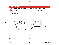
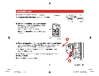
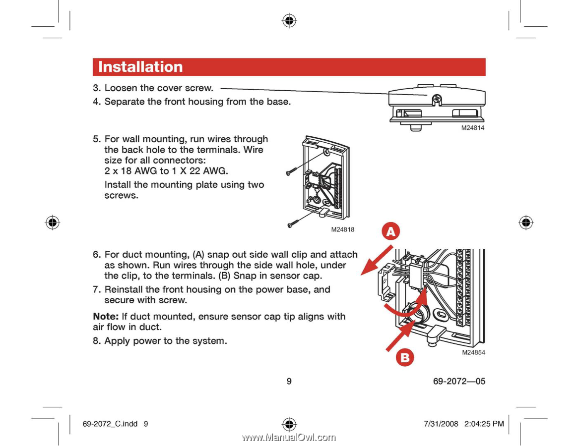
Installation 3. Loosen the cover screw. 4. Separate the front housing from the base. 5. For wall mounting, run wires through the back hole to the terminals. Wire size for all connectors: 2 x 18 AWG to 1 X 22 AWG. Install the mounting plate using two screws. M24818 6. For duct mounting, (A) snap out side wall clip and attach as shown. Run wires through the side wall hole, under the clip, to the terminals. (B) Snap in sensor cap. 7. Reinstall the front housing on the power base, and secure with screw. Note: If duct mounted, ensure sensor cap tip aligns with air flow in duct. 8. Apply power to the system. 9 M24814 A fQ, B M24854 69-2072-05 69-2072_C.indd 9 7/31/2008 2:04:25 PM
-
 1
1 -
2
-
3
-
4
-
5
-
 6
6 -
 7
7 -
 8
8 -
 9
9 -
 10
10 -
 11
11 -
 12
12 -
 13
13 -
 14
14 -
 15
15 -
 16
16 -
17
-
18
-
19
-
20
-
21
-
22
-
23
-
24
 |
 |
Installation
3.
Loosen
the
cover
screw.
4.
Separate
the
front
housing
from
the
base.
M24814
5.
For
wall
mounting,
run
wires
through
the
back
hole
to
the
terminals.
Wire
size
for
all
connectors:
2
x
18
AWG
to
1
X
22
AWG.
Install
the
mounting
plate
using
two
screws.
M24818
6.
For
duct
mounting,
(A)
snap
out
side
wall
clip
and
attach
as
shown.
Run
wires
through
the
side
wall
hole,
under
the
clip,
to
the
terminals.
(B)
Snap
in
sensor
cap.
7.
Reinstall
the
front
housing
on
the
power
base,
and
secure
with
screw.
Note:
If
duct
mounted,
ensure
sensor
cap
tip
aligns
with
air
flow
in
duct.
8.
Apply
power
to
the
system.
A
fQ,
B
M24854
9
69-2072-05
69-2072_C.indd
9
7/31/2008
2:04:25
PM