Honeywell HPTV2416UL Installation Instructions
Honeywell HPTV2416UL Manual
 |
View all Honeywell HPTV2416UL manuals
Add to My Manuals
Save this manual to your list of manuals |
Honeywell HPTV2416UL manual content summary:
- Honeywell HPTV2416UL | Installation Instructions - Page 1
Installation Document 1 Overview The Honeywell Power Products HPTV2416UL Power supply provides 16 individually servicing to qualified personnel. 3 Installation Instructions 1. Pre-drill holes where HPTV2416UL enclosure is to be mounted. If the included AC cord is used, mount the enclosure in a secure - Honeywell HPTV2416UL | Installation Instructions - Page 2
is open. Remove a camera output fuse to verify LED operation. 9. Secure the cabinet cover with metal screws to prevent access by unauthorized personnel. Wall com • Contact Technical Support: (877) HPP_POWR • Email us: [email protected] 2 HPTV2416UL Installation Instructions - P/N 52289:B1
-
 1
1 -
 2
2
 |
 |

HPTV2416UL
Power Supply
PN 52289:B1
6/5/07
ECN 06-612
Honeywell
12 Clintonville Road
Northford, CT 06472
Product Installation Document
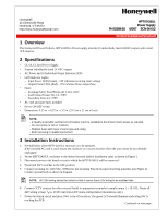
1 Overview
The Honeywell Power Products HPTV2416UL Power supply provides 16 individually fused 24VAC outputs with a total
of 8 amperes.
2 Specifications
•
UL/ULC Listed Power Supply
•
Sixteen individually fused 24 VAC outputs
•
AC Power and 16 Individual Output Indicator LEDs
•
LED Indicator Lights:
–
Input Power LED (Green) – ON indicates incoming input voltage
–
Output Power LEDs (Red) – ON indicates blown output fuse
•
Fuses
–
Incoming Safety Fuse Blocks (2) 3.15A, 250V
–
Load Output Fuses (16), 1A, 250V
–
Secondary Fuse, 4A, 250V
•
AC cord and spare fuses included
•
Power ON/OFF switch
•
Dimensions: 9.25 in. x 8.25 in. x 3.5 in. (23.3 cm x 21 cm x 9 cm)
3
Installation Instructions
1.
Pre-drill holes where HPTV2416UL enclosure is to be mounted.
If the included AC cord is used, mount the enclosure in a secure location where the unit cannot be accidentally
unplugged.
2.
Secure HPTV2416UL enclosure to the desired location (indoor installation only) as shown in Figure 1.
3.
Disconnect power to the branch circuit to which the HPTV2416UL will be connected.
4.
Place both SW1 switches to the OFF position.
5.
Connect incoming AC (120 VAC, 60Hz) into the incoming Fuse block input observing polarities (see Figure 2).
Connect ground leads as shown in diagram.
6.
Connect CCTV cameras (or other external loads) to appropriate terminals (example output 1 = 1P, 1N).
Route all
24V wiring at least
3
/
8
in. (0.953 cm) from 120V mains wiring (indoor installations only).
7.
Power the branch circuit and place SW1 to the ON position. The green LED should illuminate indicating 24V is
reaching the PCB.
NOTE:
–
A readily accessible switched circuit breaker must be available to disconnect mains power as required.
–
Do not expose to rain or moisture.
–
Replace fuses with fuses of same type and rating.
–
Refer servicing to qualified personnel.
NOTE:
All 120V wiring should be routed so that it cannot touch 24V wiring to be installed later.
Continued on next page...