Honeywell NX4S1 Installation Guide
Honeywell NX4S1 Manual
 |
View all Honeywell NX4S1 manuals
Add to My Manuals
Save this manual to your list of manuals |
Honeywell NX4S1 manual content summary:
- Honeywell NX4S1 | Installation Guide - Page 1
NetAXS™ NX4S1 Access Control Unit Installation Guide May 2007 © 2007 Honeywell. All rights reserved. 800-00008, Revision A - Honeywell NX4S1 | Installation Guide - Page 2
. All rights reserved. All product and brand names are the service marks, trademarks, registered trademarks, or registered service marks of their respective owners. Printed in the United States of America. Honeywell reserves the right to change any information in this document at any time without - Honeywell NX4S1 | Installation Guide - Page 3
16 4.5 Communications ...16 RS-232 Communications 16 RS-485 Communications 18 Ethernet TCP/IP Communications 19 4.6 DIP Switch Settings ...21 4.7 Jumper Settings...23 4.8 Downstream I/O...23 NetAXS Access Control Unit NX4S1 Installation Guide, Document 800-00008, Revision A iii - Honeywell NX4S1 | Installation Guide - Page 4
44 7.5 Common Connections 45 7.6 Mechanical...45 7.7 Environment...45 7.8 Communications and Wiring 46 7.9 Reader Wiring...46 7.10 NX4S1 Wiring Diagram 47 8.0 Maintenance...48 9.0 Troubleshooting ...48 10.0 Technical Support...49 10.1 Normal Support Hours 49 10.2 Web ...49 iv www.honeywell.com - Honeywell NX4S1 | Installation Guide - Page 5
LED Outputs 59 A.4.3 Reader Tamper Inputs 60 A.4.4 Door Egress Inputs...60 A.4.5 Door Status Inputs...61 A.4.6 ACFAIL and Panel Tamper Inputs 61 A.4.7 Additional Generic Outputs 62 NetAXS Access Control Unit NX4S1 Installation Guide, Document 800-00008, Revision A v - Honeywell NX4S1 | Installation Guide - Page 6
vi www.honeywell.com - Honeywell NX4S1 | Installation Guide - Page 7
485-PCI-2/NetAXS™ Access Controller Panel Connection Detail ..... 40 Figure 31: NetAXS™/NetAXS™ Access Controller Panel Connection Detail ......... 41 Figure 32: System, Relay and Power LEDs 42 Figure 33: NX4S1 Panel Wiring Diagram 47 NetAXS Access Control Unit NX4S1 Installation Guide, Document - Honeywell NX4S1 | Installation Guide - Page 8
viii www.honeywell.com - Honeywell NX4S1 | Installation Guide - Page 9
Settings ...22 Table 4 MIRO 32/0 DIP Switch and Jumper Settings 23 Table 5 LED Status ...43 Table 6 Communications and Wiring 46 Table 7 Reader Wiring ...46 Table 8 Troubleshooting Problems and Solutions 48 NetAXS Access Control Unit NX4S1 Installation Guide, Document 800-00008, Revision A ix - Honeywell NX4S1 | Installation Guide - Page 10
x www.honeywell.com - Honeywell NX4S1 | Installation Guide - Page 11
filed with the commercial carrier responsible. Caution: Electro-static discharge (ESD) can damage CMOS integrated circuits and modules. To prevent damage always follow these procedures: NetAXS Access Control Unit NX4S1 Installation Guide, Document 800-00008, Revision A 1 - Honeywell NX4S1 | Installation Guide - Page 12
NetAXS™ NX4S1 Installation Notices • Use static shield packaging and containers to transport all Honeywell Access Systems (HAS) include a warranty registration card which must be completed and returned to Honeywell by or on behalf of the end user in order for Honeywell to provide warranty service, - Honeywell NX4S1 | Installation Guide - Page 13
TERMS OF THIS PROVISION. IN NO EVENT SHALL HONEYWELL BE LIABLE FOR ANY RE-PROCUREMENT COSTS, LOSS the Installation Instructions or User's Manual. Unauthorized changes or modifications could void the user's authority NetAXS Access Control Unit NX4S1 Installation Guide, Document 800-00008, Revision A - Honeywell NX4S1 | Installation Guide - Page 14
NetAXS™ NX4S1 Installation Notices 1.6 Underwriters Laboratories Incorporated The NetAXS™ panel was reviewed by Underwriters Laboratories Incorporated for Access Control System Units - Category ALVY, UL294 standard. The NetAXS™ panel was reviewed as a stand alone system. The input points only - Honeywell NX4S1 | Installation Guide - Page 15
NetAXS™ NX4S1 Installation Introduction 2.0 Introduction 2.1 Access Control Overview An access control system protects and preserves an enterprise's resources by providing authentication, authorization, and administration services. Authentication is a process that verifies a user's identity. If the - Honeywell NX4S1 | Installation Guide - Page 16
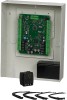
NetAXS™ NX4S1 Installation Panel Components and Descriptions 3.0 Panel Components and Descriptions The NX4S1 access control unit consists of a NetAXS™ panel control board and battery. The components are enclosed in a pre-wired cabinet. The 16.5 VAC power supply (Basler Electric Model BE156250CAA0004 - Honeywell NX4S1 | Installation Guide - Page 17
, as a fully monitored online access control device. The NetAXS™ panel also supports up to 30 downstream panels in used to power locks. For NetAXS™ maximum current draw, refer to Hardware Specifications, page 44. NetAXS Access Control Unit NX4S1 Installation Guide, Document 800-00008, Revision A - Honeywell NX4S1 | Installation Guide - Page 18
the use of a DC power supply with the NX4S1 panel. The AC input must be supplied at 16.5 VAC utilizing one of the following UL-listed, 50 VA, Class 2 transformers: Basler Electric Model BE156250CAA0004, M&G Electronics Model MGT1650 (Honeywell Access Systems part number X-4). Use a two-wire, 18 AWG - Honeywell NX4S1 | Installation Guide - Page 19
instructions in the NetAXS™ Access Control Unit User's Guide. 12.If you are using a battery backup function, place the 7 A-Hr battery in the enclosure. 13.Attach the positive (red) Power Supply-to-Battery cable to the positive (red) battery terminal. NetAXS Access Control Unit NX4S1 Installation - Honeywell NX4S1 | Installation Guide - Page 20
NetAXS™ NX4S1 Installation Installation 14.Attach the negative (black) Power Supply-to-Battery cable to the negative (black) battery terminal. 15.For panels using the Ethernet (362.50 13 3/4" (343.75 mm) 12 9/16" (318.75 mm) 7 1/8" (181.25 mm) 1 23/32" (43.75 3/4" (18.75 mm) 0 10 www.honeywell.com - Honeywell NX4S1 | Installation Guide - Page 21
14/16" ( 21.875 mm) diameter knockout 1 16/32" (38.275 mm) Back 14 9/32" (362.5 mm) 13 9/32" (337.5 mm) 31/32" (25 mm) 0 NetAXS Access Control Unit NX4S1 Installation Guide, Document 800-00008, Revision A 11 - Honeywell NX4S1 | Installation Guide - Page 22
NetAXS™ NX4S1 Installation Installation Figure 5: NetAXS™ Panel Cabinet, Left View 4 11/32" (110 mm) 0 Back 7/8" (21.875 mm) diameter knockout 1 15/32" (37.5 mm) 3/4" (18.75 mm) 12 www.honeywell.com - Honeywell NX4S1 | Installation Guide - Page 23
Figure 6: NetAXS™ NX4S1Panel Cabinet, Right View NetAXS™ NX4S1 Installation Installation 0 4 11/32" (110 mm) Back 7/8" (21.875 mm) diameter knockout 0 3/4" (18.75 mm) 4 7/32" (107.5 mm) NetAXS Access Control Unit NX4S1 Installation Guide, Document 800-00008, Revision A 13 - Honeywell NX4S1 | Installation Guide - Page 24
NetAXS™ NX4S1 Installation Installation 4.2 Reader Wiring Each reader port supports a single 12-volt reader with Wiegand output format. Power to the readers is shared with Position Default Function TB4-1 Door 1 REX (Egress) TB4-3 Door 1 Status TB4-4 Door 2 REX (Egress) 14 www.honeywell.com - Honeywell NX4S1 | Installation Guide - Page 25
7: Typical Supervised Input Wiring Diagram NO 2.2K 2.2K NC 2.2K 2.2K TB 4 1 DOOR 1 EGRESS 2 the same value. See the NetAXS™ Access Control Unit User's Guide for instructions on selecting resistor options. NetAXS Access Control Unit NX4S1 Installation Guide, Document 800-00008, Revision A 15 - Honeywell NX4S1 | Installation Guide - Page 26
lock, and Relay 4 is defaulted for the control of the Door 4 lock. Relays 5-8 are used as auxiliary relays. Refer to the NetAXS™ Access Control Unit User's Guide for details on controlling the relay operations. Each relay also has a green indicator LED, which indicates the relay state. If the relay - Honeywell NX4S1 | Installation Guide - Page 27
your Honeywell Access System Representative. Figure 8: RJ-45 Serial Port Figure 9: RS-232 Configuration Terminal COM1 CBL50 NetAXS Panel COM2 NetAXS Panel One NetAXS panel per COM port. Two COM ports possible. Reader 1 Reader 4 Reader 1 Reader 4 NetAXS Access Control Unit NX4S1 Installation - Honeywell NX4S1 | Installation Guide - Page 28
NetAXS™ NX4S1 Installation Installation RS-485 Communications The NetAXS™ panel can reside on an existing RS-485 drop line hosted by either a NetAXS™ NetAXS Panel A combination of N1000 III, N1000 IV, NS2+ and NewAXS panels, supporting a total of 31 panels per multi-drop line 18 www.honeywell - Honeywell NX4S1 | Installation Guide - Page 29
TCP/IP interface (see Figure 12, Ethernet TCP/IP Configuration). The Ethernet TCP/IP interface provides 10/100 Mbit Ethernet support for each panel. Up to 31 panels can be configured on each TCP/IP connection. NetAXS Access Control Unit NX4S1 Installation Guide, Document 800-00008, Revision A 19 - Honeywell NX4S1 | Installation Guide - Page 30
NetAXS™ NX4S1 Installation Installation Figure 13 on page 20 shows the location of the panel's unique MAC ID. Figure 13: Ethernet MAC Address Location Label with Ethernet MAC Address 20 www.honeywell.com - Honeywell NX4S1 | Installation Guide - Page 31
NetAXS™ NX4S1 Installation Installation 4.6 DIP Switch Settings Figure 14 on page 21 locates the NX4S1 DIP switch panel and the J36 and J37 (termination and biasing) jumpers. Figure 14: DIP Switch and Jumper Locations J37 J36 DIP Switches NetAXS Access Control Unit NX4S1 Installation Guide, - Honeywell NX4S1 | Installation Guide - Page 32
NetAXS™ NX4S1 Installation Installation Use the following DIP switch configurations to set the panel address. Table 3 DIP on on on Address 30 on on on on on Address 31 off NetAXS™ Multidrop on NetAXS™ Gateway Note: Address 0 is not a valid setting for standard operations. 22 www - Honeywell NX4S1 | Installation Guide - Page 33
resistance. Refer to the individual installation manuals for I/O wiring details. The downstream I/O bus is wired into the NetAXS™ TB10 terminal block. The 8 = ON OP Mode (switches 9 and 10) - 9 = OFF, 10 = OFF NetAXS Access Control Unit NX4S1 Installation Guide, Document 800-00008, Revision A 23 - Honeywell NX4S1 | Installation Guide - Page 34
NetAXS™ NX4S1 Installation Installation other than 1 or 2, the NetAXS™ panel will not communicate with it. Likewise, if a MIRO 2/ 3 through 6, the NetAXS™ panel will not communicate with it. The NetAXS™ board is not For some installations, the noise immunity improves if the NetAXS™ common is - Honeywell NX4S1 | Installation Guide - Page 35
the default downstream I/O system configuration with communication and power wiring. This configuration has not been reviewed by UL. Figure 15: Default Downstream I/O Configuration with Wiring NetAXS Access Control Unit NX4S1 Installation Guide, Document 800-00008, Revision A 25 - Honeywell NX4S1 | Installation Guide - Page 36
NetAXS™ NX4S1 Installation System Configuration 5.0 System Configuration This section provides wiring diagrams for each of the NetAXS™ system configurations. 5.1 RS-485 Connection via PCI-2 This connection supports thirty-one NetAXS™ Access Controller panels for each drop line. It has been reviewed - Honeywell NX4S1 | Installation Guide - Page 37
NetAXS™ NX4S1 Installation System Configuration 5.2 RS-485 Connection via NetAXS™ This connection supports thirty-one NetAXS™ Access Controller panels for each drop line. It has been reviewed by UL. However, because UL has reviewed the NetAXS™ panel only as a standalone system, the computer terminal - Honeywell NX4S1 | Installation Guide - Page 38
NetAXS™ NX4S1 Installation System Configuration 5.3 RS-485 Connections with Multidrop Panels at Both Ends of the Cable You can connect Multidrop panels at both ends of an RS-485 cable via either a NetAXS NetAXS™ with Multidrop Panels at Both Ends COM Port Terminal RS-485 Cable NetAXS NetAXS Panel - Honeywell NX4S1 | Installation Guide - Page 39
S1-S5 Panel Address S6: OFF J36 OPEN J37 OPEN NetAXS Panel EG EG n y ar roun one side of cable EG EG one side of cable EG EG It is recommended to Earth Ground (EG) each NetAXS enclosure individually NetAXS Access Control Unit NX4S1 Installation Guide, Document 800-00008, Revision A 29 - Honeywell NX4S1 | Installation Guide - Page 40
NetAXS™ NX4S1 Installation System Configuration 5.4 RS-232 Connection This connection supports one NetAXS™ Access Controller panel for each COM port. It has been reviewed by UL. However, because UL has reviewed the NetAXS™ panel only as a standalone system, the computer terminal and NetAXS™ gateway - Honeywell NX4S1 | Installation Guide - Page 41
21: Ethernet Connection NIC Terminal RS-485 Multidrop 100BaseT (CAT 5) 328 Ft. Max. DIP Switch Settings S1-S5 Panel Address S6: OFF RS-485 Multidrop NetAXS Panel EG EG EG EG NetAXS Access Control Unit NX4S1 Installation Guide, Document 800-00008, Revision A 31 - Honeywell NX4S1 | Installation Guide - Page 42
NetAXS™ NX4S1 Installation System Configuration 5.6 LANSRLU1 Connection This connection supports NIC Terminal HUB/SWITCH HUB/SWITCH RS-485 Cable RS485 NetAXS Panels Red/White Black/Green RS-485 COM TB7-1 NetAXS enclosure individually Only Earth Ground (EG) EG one side of cable EG 32 www - Honeywell NX4S1 | Installation Guide - Page 43
NetAXS™ NX4S1 Installation System Configuration 5.7 RS-485 Short Haul Modem Connection via PCI-2 This connection supports thirty-one NetAXS™ Access Controller Comm 2 (TX) 2 (RX) 3 (RX) or 3 (TX) 7 (GND) 7 (GND) NetAXS Access Control Unit NX4S1 Installation Guide, Document 800-00008, Revision A 33 - Honeywell NX4S1 | Installation Guide - Page 44
NetAXS™ NX4S1 Installation System Configuration 5.8 RS-485 Short Haul Modem Connection via NetAXS™ Thirty-one NetAXS™ Access Controller panels for each drop line. It has not been reviewed by UL. Figure 24: RS-485 Short Haul Modem Connection via NetAXS Loopback) NetAXS EG Panel NetAXS EG NetAXS - Honeywell NX4S1 | Installation Guide - Page 45
DIS (Jumper) (J1 RS-232 Connector) RS232 Cable MODEM PC (DB-9) DTE DCE (Straight) (Null) 2 TX 3 RX 5 Comm 2 (TX) 2 (RX) 3 (RX) or 3 (TX) 7 (GND) 7 (GND) NetAXS Access Control Unit NX4S1 Installation Guide, Document 800-00008, Revision A 35 - Honeywell NX4S1 | Installation Guide - Page 46
NetAXS™ NX4S1 Installation System Configuration 5.10 M-56K Dial-up Modem, RS-485 Connection via Hub Thirty-one NetAXS™ Access recommended Refer to 485PCI-2 /NetAXS Panel Connection Detail diagram OPEN NetAXS Panel EG NetAXS Panel EG 14 1 96 96 RS-485 Cable NetAXS Panels TB7-1 (RS485+) TB7-2 ( - Honeywell NX4S1 | Installation Guide - Page 47
25 5 14 1 25 5 14 1 96 96 RS-485 Cable NetAXS Panels TB7-1 (RS485+) TB7-2 (RS485-) TB7-3 (RS485 COM) 4,000 ft. (1,200 m) max, 24 AWG, 2 twisted pairs with shield, 120 ohm, 23 pf (HAS part no. NCP2441-TN) NetAXS Access Control Unit NX4S1 Installation Guide, Document 800-00008, Revision A 37 - Honeywell NX4S1 | Installation Guide - Page 48
NetAXS™ NX4S1 Installation System Configuration 5.12 Fiber Converter to RS-485 Connection via PCI-2 This connection supports thirty-one NetAXS™ Access 485-PCI-2/NetAXS Access Controller Panel each NetAXS enclosure Individually NetAXS TXD RS-485 Cable RS485 NetAXS Panels Red/White Black/Green - Honeywell NX4S1 | Installation Guide - Page 49
NetAXS™ NX4S1 Installation System Configuration 5.13 Fiber Converter to RS-485 Connection via NetAXS™ This connection supports thirty-one NetAXS™ Access Controller panels for each drop line. It has not been reviewed by UL. Figure 29: Fiber Converter to RS-485 Connection via NetAXS™ COM Port RS- - Honeywell NX4S1 | Installation Guide - Page 50
NX4S1 Installation System Configuration 5.14 N-485-PCI-2/NetAXS™ Access Controller Panel Connection Detail This diagram has not been reviewed by UL. Note that PCI-2 units can also be wired anywhere along the drop line. See Figure 18 on page 28 and Figure 19 on page 29. Figure 30: N-485-PCI-2/NetAXS - Honeywell NX4S1 | Installation Guide - Page 51
3 1 2 DO NOT CONNECT SHIELD X 485 Common Shield 485 + 485 - NetAXS TB7 Ground only one side of cable shield 4,000 ft.(1,200 m) max,24 AWG,2 twisted pairs with shield,120 ohm,23 pf (NCI part no.NCP2441-TN) NetAXS Access Control Unit NX4S1 Installation Guide, Document 800-00008, Revision A 41 - Honeywell NX4S1 | Installation Guide - Page 52
NetAXS™ NX4S1 Installation NetAXS™ Startup 6.0 NetAXS™ Startup 6.1 LED Operation When the panel wiring is complete, turn on the power. It might take a few minutes for the RS232 and Downstream LEDs RDR 3 RDR 4 RS485 LED RDR 1 RDR 2 Relay Status LEDs Relay Status LEDs Power 42 www.honeywell.com - Honeywell NX4S1 | Installation Guide - Page 53
NetAXS™ NX4S1 Installation NetAXS™ Startup The following table indicates the status associated with each LED. Table 5 LED Status Note: The Ethernet/COM status LED will be green even if no cable is attached. NetAXS Access Control Unit NX4S1 Installation Guide, Document 800-00008, Revision A 43 - Honeywell NX4S1 | Installation Guide - Page 54
NetAXS™ NX4S1 Installation Hardware Specifications 7.0 Hardware Specifications 7.1 Relay Contacts Four Form-C SPDT relays: • 10 A @ 28 VDC resistive load • 5 A @ 28 VDC separate power supply. • A UL-listed system's power supply must also be UL-listed for this application. 44 www.honeywell.com - Honeywell NX4S1 | Installation Guide - Page 55
NetAXS™ NX4S1 Installation Hardware Specifications 7.5 Common Connections Common connections are all connected internally. They Temperature: 0C to 49C operating, -55C to +85C storage. • Humidity: 5% to 85% RHNC. NetAXS Access Control Unit NX4S1 Installation Guide, Document 800-00008, Revision A 45 - Honeywell NX4S1 | Installation Guide - Page 56
NetAXS™ NX4S1 Installation Hardware Specifications 7.8 Communications and Wiring Table 6 Communications and Wiring Communication Type Description Maximum Panels Maximum Distance: AWG Maximum Distance: Feet (Meters) 18 500 (153) 18 2,000 (610) 18 2,000 (610) 46 www.honeywell.com - Honeywell NX4S1 | Installation Guide - Page 57
least a .25-inch distance between the non-power limited wiring (battery backup/charger wiring) and all other wiring, which is power-limited Class 2 wiring. Input * NetAXS Access Control Unit NX4S1 Installation Guide, Document 800-00008, Revision A 47 - Honeywell NX4S1 | Installation Guide - Page 58
on the NetAXS™ enclosure: • Change the CASIL CA1270 lead-acid battery (Honeywell Access Systems part number 3-000066) every two to two and a half years. Caution: Do not connect an uncharged battery to the panel. • Oil the lock once per year. 9.0 Troubleshooting Table 8 Troubleshooting Problems and - Honeywell NX4S1 | Installation Guide - Page 59
NetAXS™ NX4S1 Installation Technical Support Table 8 Troubleshooting Problems and Solutions Problem Solution A dropline panel in standalone mode using RS-232 may unexpectedly fill its buffer. The preferred solution is to configure the standalone panel through the - Honeywell NX4S1 | Installation Guide - Page 60
NetAXS™ NX4S1 Installation Technical Support 50 www.honeywell.com - Honeywell NX4S1 | Installation Guide - Page 61
A NetAXS™ Standalone Operation A.1 Basic Standalone Operations A.1.1 Card Read / Door Lock Operation 1. Present a card to a reader. 2. The the 10 second door open period, the door relay will be immediately de-energized. NetAXS Access Control Unit NX4L1 Installation Guide, 7-901099, Revision A 51 - Honeywell NX4S1 | Installation Guide - Page 62
personal computer's serial communications port (COM1 or COM2) and a terminal emulation program to configure the NetAXS™ panel for normal operation. A.2.2 Communication Settings • Baud Rate: 115200 • Data Bits: 8 • indicates proper communication between the terminal and panel. 52 www.honeywell.com - Honeywell NX4S1 | Installation Guide - Page 63
or Deletes cards from the panel 5. W command: Program each input for either NO/NC and Supervised or NON Supervised operation 6. P command: Sets interlocks between input points and/ would set panel 6 to a time of 6:15 PM. NetAXS Access Control Unit NX4L1 Installation Guide, 7-901099, Revision A 53 - Honeywell NX4S1 | Installation Guide - Page 64
NetAXS™ Standalone Operation Standalone Commands A.3.2 D (Date) Command _D=pn_mm/dd/yyyy_day Variables: pn = panel number (1-31) mm = month number (1-12) dd = day number 14/2009_7 This command would set panel 25 to a date of 12/14/2009 with a day of week being Monday. 54 www.honeywell.com - Honeywell NX4S1 | Installation Guide - Page 65
commands we can simulate this. For more information, please seek the guidance of technical support. Example #1: _L=5_10_08:00-17:00_1_2_3_4_5 This command would configure panel 5 to , Sunday, Holiday, 1, 2, and 3. NetAXS Access Control Unit NX4L1 Installation Guide, 7-901099, Revision A 55 - Honeywell NX4S1 | Installation Guide - Page 66
NetAXS™ Standalone Operation Standalone Commands A.3.4 C (Card Add) Command _C=pn_code_time zone_dev Variables: pn = panel number (1-31) code = card number (range remove card 12345 from panel 6. Example #2 _C=18_52989 This command would remove card 52989 from panel 18. 56 www.honeywell.com - Honeywell NX4S1 | Installation Guide - Page 67
NetAXS™ Standalone Operation Standalone Commands A.3.6 W (Input) Command _W=pn_input_{SO|SC|NO|NC} Variables: SO: Supervised normally open SC: Supervised normally closed NO: Non-supervised normally open NC -energizes. NetAXS Access Control Unit NX4L1 Installation Guide, 7-901099, Revision A 57 - Honeywell NX4S1 | Installation Guide - Page 68
NetAXS™ Standalone Operation Standalone Commands A.3.8 Flow Control Disable/Enable (Use this command only for a dropline panel using RS-232 in standalone mode) _U=[panel prevents the panel's buffers from filling. After a hard re-set of the panel, the flow control is re-enabled. 58 www.honeywell.com - Honeywell NX4S1 | Installation Guide - Page 69
™ Standalone Operation NetAXS™ Panel Defaults A.4 NetAXS™ Panel Defaults A.4.1 Reader Ports The panel accepts a Wiegand serial data packet Reader 2 Reader 3 Reader 4 Controls... Output 11 Output 12 Output 13 Output 14 NetAXS Access Control Unit NX4L1 Installation Guide, 7-901099, Revision A 59 - Honeywell NX4S1 | Installation Guide - Page 70
Panel Defaults A.4.3 Reader Tamper Inputs The card readers have a Tamper signal wired to the NetAXS™ panel. This is a two-state input configured as a Normally Closed contact. The relay... 1 2 3 4 Panel input SP1 SP3 SP5 SP7 Reports as... Input 1 Input 3 Input 5 Input 7 60 www.honeywell.com - Honeywell NX4S1 | Installation Guide - Page 71
™ Standalone Operation NetAXS™ Panel Defaults A.4.5 Door Status Inputs The panel has a Door Status input for each door. The default Generic/Enclosure Tamper Panel input SP9 SP10 Reports as... Input 13 Inputs 14 and 20 NetAXS Access Control Unit NX4L1 Installation Guide, 7-901099, Revision A 61 - Honeywell NX4S1 | Installation Guide - Page 72
NetAXS™ Standalone Operation NetAXS™ Panel Defaults A.4.7 Additional Generic Outputs The panel has the following four additional generic form C relay outputs that can be programmed using the P command: Relay output 5 6 7 8 Controls... Output 5 Output 6 Output 7 Output 8 62 www.honeywell.com - Honeywell NX4S1 | Installation Guide - Page 73
Honeywell Access Systems 135 W. Forest Hill Avenue Oak Creek, WI 53154 United States 800-323-4576 414-766-1798 Fax www.honeywellaccess.com Specifications subject to change without notice. © Honeywell. All rights reserved. Document 800-00008, Revision A
-
 1
1 -
 2
2 -
 3
3 -
 4
4 -
 5
5 -
 6
6 -
 7
7 -
8
-
9
-
10
-
11
-
12
-
13
-
14
-
15
-
16
-
17
-
18
-
19
-
20
-
21
-
22
-
23
-
24
-
25
-
26
-
27
-
28
-
29
-
30
-
31
-
32
-
33
-
34
-
35
-
36
-
37
-
38
-
39
-
40
-
41
-
42
-
43
-
44
-
45
-
46
-
47
-
48
-
49
-
50
-
51
-
52
-
53
-
54
-
55
-
56
-
57
-
58
-
59
-
60
-
61
-
62
-
63
-
64
-
65
-
66
-
67
-
68
-
69
-
70
-
71
-
72
-
73
 |
 |

May 2007
© 2007 Honeywell. All rights reserved.
800-00008, Revision A
NetAXS™
NX4S1
Access Control Unit
Installation Guide