Honeywell NX4S1 Installation Guide - Page 28
RS-485 Communications
 |
View all Honeywell NX4S1 manuals
Add to My Manuals
Save this manual to your list of manuals |
Page 28 highlights
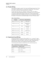
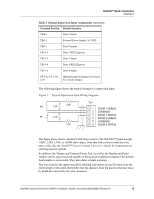
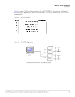
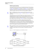
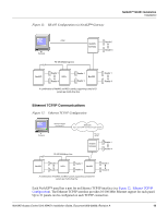
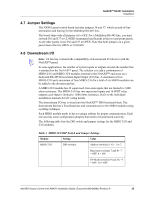
NetAXS™ NX4S1 Installation Installation RS-485 Communications The NetAXS™ panel can reside on an existing RS-485 drop line hosted by either a NetAXS™ panel configured as a Gateway, or N-485-PCI-2, PCI-3, or N-485-HUB-2 (see Figure 10 on page 18, Figure 11 on page 19, and Figure 23 on page 33). The interface allows the wiring of a Multidrop communication network of up to 4,000 feet (1200 m) in length. Only one host converter device per dropline is supported. Note: On a Multidrop line, the Gateway panel and the PCI unit can have either end-point or interior positions. See Figure 18 on page 28 and Figure 19 on page 29 for illustrations. DIP switch position 6 on the NetAXS™ panel selects whether the panel is a Gateway or Multidrop panel. The switch in the OFF position configures the panel as a Multidrop panel; ON configures a Gateway. The panel must be power cycled for a new switch setting to be recognized. DIP switch positions 1-5 are used to select the panel's address on the network. Refer to Table 3 for DIP switch setting information. Connectors J36 and J37 are provided for supplying biasing and end-of-line termination for the RS-485 network. The board ships with all jumpers open. For a Multidrop RS-485 line, you must close both J36 and J37 (terminated and biased) at the two end-point panels. At all other panels, leave J36 and J37 open. Both jumpers on a given panel must set the same. Note that biasing and termination on both ends are present. Use the jumpers on both ends of the RS-485 network. Note: If an RS-485 network has a NetAXS™ Gateway panel, no N1000-II, N1000-III, or N1000-IV are allowed on the same network. If they are added to a network with a NetAXS™ Gateway panel, they will not be able to communicate with the host computer. Figure 10: RS-485 Configuration via N-485-PCI-2 or PCI-3 N-485-PCI-2/3 COM1 Terminal RS-485 Multidrop Line N1000 III N1000 IV Reader 1 Reader 2 NS2+ Panel Reader 1 Reader 2 NetAXS Panel A combination of N1000 III, N1000 IV, NS2+ and NewAXS panels, supporting a total of 31 panels per multi-drop line 18 www.honeywell.com Reader 1 Reader 4
-
 1
1 -
2
-
3
-
4
-
5
-
6
-
7
-
8
-
9
-
10
-
11
-
12
-
13
-
14
-
15
-
16
-
17
-
18
-
19
-
20
-
21
-
22
-
 23
23 -
 24
24 -
 25
25 -
 26
26 -
 27
27 -
 28
28 -
 29
29 -
 30
30 -
 31
31 -
 32
32 -
 33
33 -
34
-
35
-
36
-
37
-
38
-
39
-
40
-
41
-
42
-
43
-
44
-
45
-
46
-
47
-
48
-
49
-
50
-
51
-
52
-
53
-
54
-
55
-
56
-
57
-
58
-
59
-
60
-
61
-
62
-
63
-
64
-
65
-
66
-
67
-
68
-
69
-
70
-
71
-
72
-
73
 |
 |