Honeywell T4398A1021 User Guide - Page 5
Checkout - security
 |
UPC - 085267088442
View all Honeywell T4398A1021 manuals
Add to My Manuals
Save this manual to your list of manuals |
Page 5 highlights
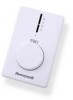
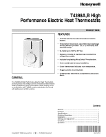
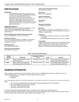
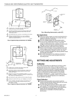
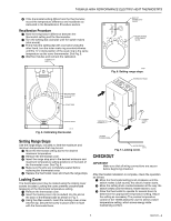
5 12 50 T4398A,B HIGH PERFORMANCE ELECTRIC HEAT THERMOSTATS ᕤ If the thermostat setting differs from the thermometer, record the temperature difference and recalibrate as instructed in the Recalibration Procedure section. Recalibration Procedure ᕡ Note the temperature difference between the thermostat setting and the thermometer. ᕢ Turn the setting dial clockwise until the switch makes (click sound). ᕣ Firmly hold the setting dial with one hand. Using the other hand, turn the outer scale ring counterclockwise until the 12 o'clock position of the scale ring is the same temperature as the cover thermometer. See Fig. 5. ᕤ Wait five minutes and recheck the calibration. THERMOSTAT BASE 2475 BACK OF THERMOSTAT COVER 65 70 20˚C 16 60 5 INSERT RANGE STOP PINS IN SLOTS. M5801 Fig. 6. Setting range stops. THERMOSTAT BASE 75 70 65 60 80 55 SETTING KNOB AT 12 O'CLOCK POSITION SCALE RING SETTING KNOB THERMOSTAT COVER LOCKING COVER CLIP M5796 Fig. 5. Calibrating thermostat. Setting Range Stops Use the range stops, included, to limit the maximum and minimum temperatures that may be set. ᕡ Move the thermostat setting dial to the desired maximum temperature. ᕢ Remove the thermostat cover. ᕣ Insert the range stop pins in the desired minimum and maximum temperature setting positions on the back of the thermostat cover. See Fig. 6. ᕤ Make sure the pins are completely seated before replacing the thermostat cover. ᕥ Replace the thermostat cover and check the range stops. Locking Cover The thermostat cover may be locked using the locking cover screws included. Locking the cover prevents unauthorized tampering of the thermostat temperature setting. ᕡ Remove the thermostat cover. ᕢ Insert the locking cover clip (included) into the slot at the back of thermostat base as shown in Fig. 7. ᕣ Using the Allen wrench, insert the locking cover screw into the clip. Secure the screw in place until it is flush with the thermostat base. LOCKING COVER SCREW ALLEN WRENCH M5798 Fig. 7. Locking cover. CHECKOUT IMPORTANT Make sure that all wiring connections are secure before beginning checkout. After thermostat installation is complete, check the operation as follows: ᕡ Move the thermostat setting knob clockwise until the switch makes (click sound); the electric heater starts. ᕢ Move the setting knob counterclockwise all the way; the switch breaks and the electric heater starts to cool. ᕣ Allow the thermostat to operate for several hours to determine the appropriate temperature setting. Adjust the setting as necessary. The precise temperature control of the T4398 allows the user to select a lower temperature setting, which saves energy while maintaining comfort. 5 68-0147-2
-
 1
1 -
 2
2 -
 3
3 -
 4
4 -
 5
5 -
 6
6 -
 7
7 -
 8
8
 |
 |