Honeywell T812C1000 Installation Instructions
Honeywell T812C1000 - Premier 1 Heat/1 Cool Stage Thermostat Manual
 |
View all Honeywell T812C1000 manuals
Add to My Manuals
Save this manual to your list of manuals |
Honeywell T812C1000 manual content summary:
- Honeywell T812C1000 | Installation Instructions - Page 1
not place your old control in the trash. Contact your local waste management authority for instructions regarding recycling and the proper disposal of the old thermostat. INSTALLATION INSTRUCTIONS INSTALLATION When Installing this Product... 1. Read these instructions carefully. Failure to follow - Honeywell T812C1000 | Installation Instructions - Page 2
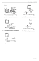
HOLES (2) USED TO MOUNT THERMOSTAT TO WALL (FOR MODELS WITH SUBBASE). SCREWS (3) USED TO MOUNT THERMOSTAT ONTO SUBBASE BIMETAL ELEMENT ADJUSTABLE HEAT ANTICIPATOR INDICATOR LEVER ADJUSTABLE HEAT ANTICIPATOR SCALE MOUNTING HOLE (THERMOSTAT TO WALL) M20496A Fig. 1. Internal view of T812 with - Honeywell T812C1000 | Installation Instructions - Page 3
REQUIRED. M20437 Fig. 4. T812A in typical gas heating system. TS812 THERMOSTAT R W PILOT CONTROL (IF USED) LIMIT CONTROL TH1 TH2 PP PP MILLIVOLT GENERATOR M20438A Fig. 5. Typical hookup to TS812A in millivolt system. T812B THERMOSTAT WR TO 12 Vdc 1 POWER SUPPLY GAS VALVE 1 POWER SUPPLY - Honeywell T812C1000 | Installation Instructions - Page 4
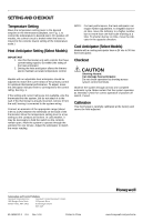
the indicator in the opposite direction. Cool Anticipator (Select Models) Models with a cooling anticipator have a 24 Vac to 30 thermostat is carefully calibrated at the factory and cannot be field-adjusted. Automation and Control Solutions Honeywell International Inc. Honeywell Limited-Honeywell - Honeywell T812C1000 | Installation Instructions - Page 5
o de otros aparatos. - tuberías y chimeneas ocultas. - área sin calefacción (enfriamiento) tal como una pared exterior detrás del termostato. ® Marca registrada en los E.U.A. Copyright © 2004 Honeywell International Inc. Todos los derechos reservados 69-1606ESF-3 - Honeywell T812C1000 | Installation Instructions - Page 6
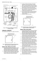
selectos) para que concuerde con el consumo de corriente del control primario del sistema. Consulte la sección sobre Configuración del precisión. 8. Apriete los tornillos de instalación. Consulte la Figura 3. 9. Instale el termostato en la base inferior apretando los tres tornillos. Consulte la - Honeywell T812C1000 | Installation Instructions - Page 7
UNA SOBRECARGA, SEGÚN SE REQUIERA. MS20437 Fig. 4. T812A en un sistema típico de calefacción por gas. TERMOSTATO TS812 RB CONTROL DE PILOTO (SI SE USA) CONTROL DE LÍMITE TM1 TM2 PP PP GENERADOR DE MILIVOLTIOS MS20438A Fig. 5. Conexión típica al TS812A en sistema de milivoltios. TERMOSTATO - Honeywell T812C1000 | Installation Instructions - Page 8
calibrado cuidadosamente en la fábrica por lo que no puede ajustarse en el campo. Soluciones de automatización y control Honeywell International Inc. Honeywell Limited-Honeywell Limitée 1985 Douglas Drive North 35 Dynamic Drive Golden Valley, MN 55422 Scarborough, Ontario M1V 4Z9 69-1606ESF - Honeywell T812C1000 | Installation Instructions - Page 9
à la poubelle. Communiquer avec le service d'enlèvement des déchets de la municipalité pour savoir comment recycler ce type de thermostat et comment en disposer. NOTICE D'INSTALLATION INSTALLATION Avant d'installer ce produit... 1. Lire attentivement les présentes instructions. Le fait de ne pas - Honeywell T812C1000 | Installation Instructions - Page 10
é ni effiloché; remplacer tous les fils abîmés. Dans le cas d'une nouvelle installation, amener les deux fils jusqu'à l'emplacement choisi. 2. Saisir d'une main la partie supérieure et la partie inférieure du couvercle du thermostat, appuyer sur la partie inférieure, au centre, et tirer pour dégager - Honeywell T812C1000 | Installation Instructions - Page 11
AU BESOIN UN DISPOSITIF DE COUPURE ET UNE PROTECTION CONTRE LES SURCHARGES MF20437 Fig. 4. T812A dans un système de chauffage au gaz typique. THERMOSTAT TS812 R W RÉGULATEUR DE VEILLEUSE (LE CAS ÉCHÉANT) LIMITEUR TH1 TH2 PP PP GÉNÉRATEUR À TENSION MV MF20438A Fig. 5. Schéma de raccordement - Honeywell T812C1000 | Installation Instructions - Page 12
avec position de fermeture fonctionne correctement. Étalonnage Ce thermostat a été étalonné avec soin à l'usine; il ne peut être réglé en clientèle. Solutions de régulation et d'automatisation Honeywell International Inc. Honeywell Limited-Honeywell Limitée 1985 Douglas Drive North 35, Dynamic
-
 1
1 -
 2
2 -
 3
3 -
 4
4 -
 5
5 -
 6
6 -
 7
7 -
8
-
9
-
10
-
11
-
12
 |
 |

® U.S. Registered Trademark
Copyright © 2004 Honeywell International Inc.
•
• All Rights Reserved
INSTALLATION INSTRUCTIONS
69-1606ESF-3
T812, TS812 Thermostats
APPLICATION
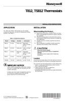
The T812 and TS812 Thermostats are low voltage,
controls for heat only, cool only or heating and cooling
systems. See Table 1.
MERCURY NOTICE
If this control is replacing a control that contains
mercury in a sealed tube, do not place your old
control in the trash.
Contact your local waste management authority
for instructions regarding recycling and the
proper disposal of the old thermostat.
INSTALLATION
When Installing this Product...
1.
Read these instructions carefully. Failure to follow
them could damage the product or cause a hazard-
ous condition.
2.
Check the ratings given in the instructions and on
the product to make sure the product is suitable for
your application.
3.
Installer must be a trained, experienced service
technician.
4.
After installation is complete, check out product
operation as provided in these Instructions.
CAUTION
Electrical Shock Hazard.
Can cause personal injury or equipment
damage.
Disconnect power supply before beginning
installation.
Location
Locate the thermostat about 5 ft (1.5m) above the floor in
an area with good air circulation at average temperature.
Do not mount the thermostat where it can be affected by:
— drafts, or dead spots behind doors and in corners.
— hot or cold air from ducts.
— radiant heat from the sun or appliances.
— concealed pipes and chimneys.
—
unheated (uncooled) area such as outside wall behind
the thermostat.
Table 1. Model Descriptions.
Model
Voltage
System
Anticipator
T812A
24 Vac
Heat only
Adjustable
.18A to 1.2A @
30 Vac
T812B
12 Vdc
Heat only
.18A to 1.2A @
12 Vdc
T812C
24 Vac
Heat and
Cool
Adjustable
.18A to 1.2A @
30 Vac
T812D
24 Vac
Cool only
Fixed 24 Vac to
30 Vac
TS812A
750 mV
Heat only
.1A @ .75 Vdc